Protecting device of bicycle frame
A protective device and frame technology, which can be used in weather guards, bicycle accessories, transportation and packaging, etc., can solve the problems of lost bags, insecurity, etc., and achieve the effect of simple seating, improved safety, and good protection
- Summary
- Abstract
- Description
- Claims
- Application Information
AI Technical Summary
Problems solved by technology
Method used
Image

Examples
Example Embodiment
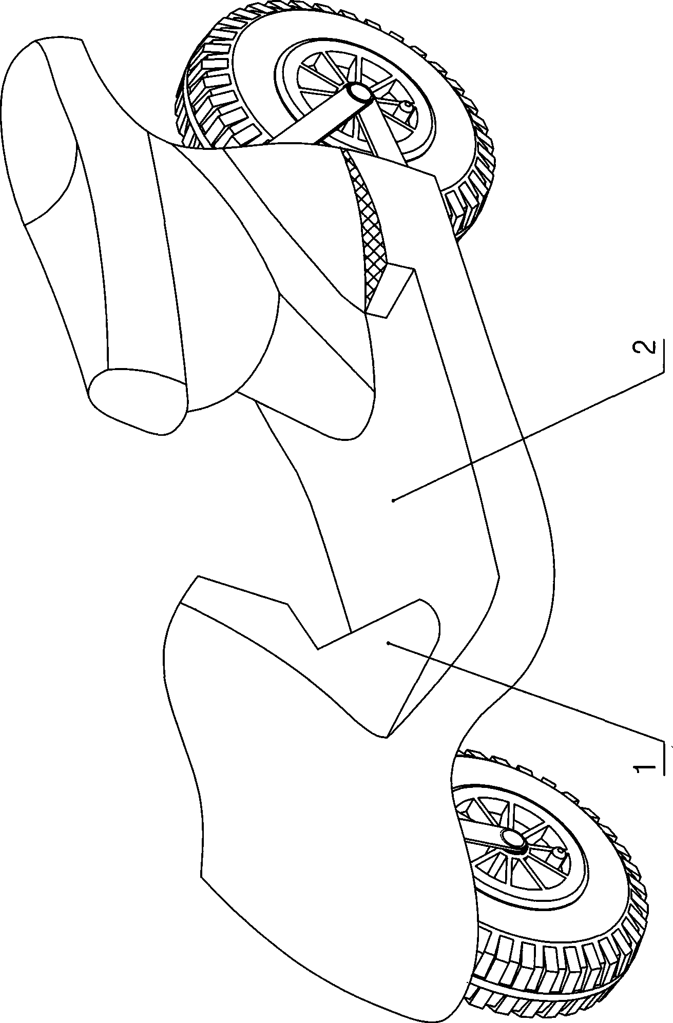
[0021] Example 1:
[0022] Such as figure 2 As shown, the protective device on the frame of the present invention includes: a pedal 2 arranged in the middle of the frame 1, and a protective plate 3 is arranged on one side of the pedal 2.
Example Embodiment
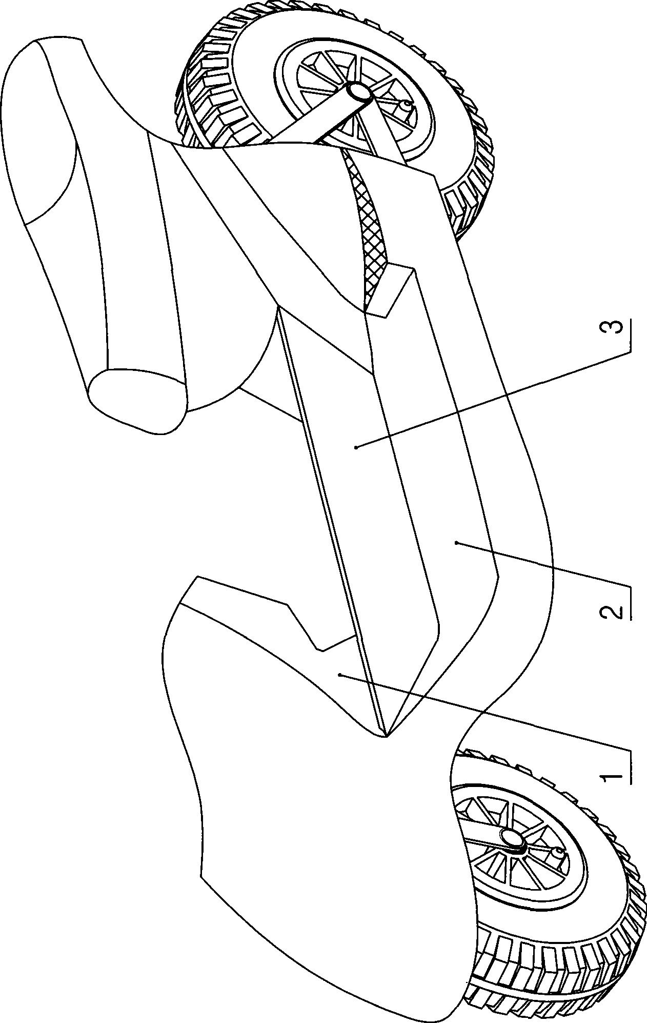
[0023] Example 2:
[0024] Such as image 3 As shown, the protective device on the frame of the present invention includes: a pedal 2 arranged in the middle of the frame 1, a protective plate 3 is provided on both sides of the pedal 2, two protective plates 3 and the frame A protective room is formed between 1.
Example Embodiment
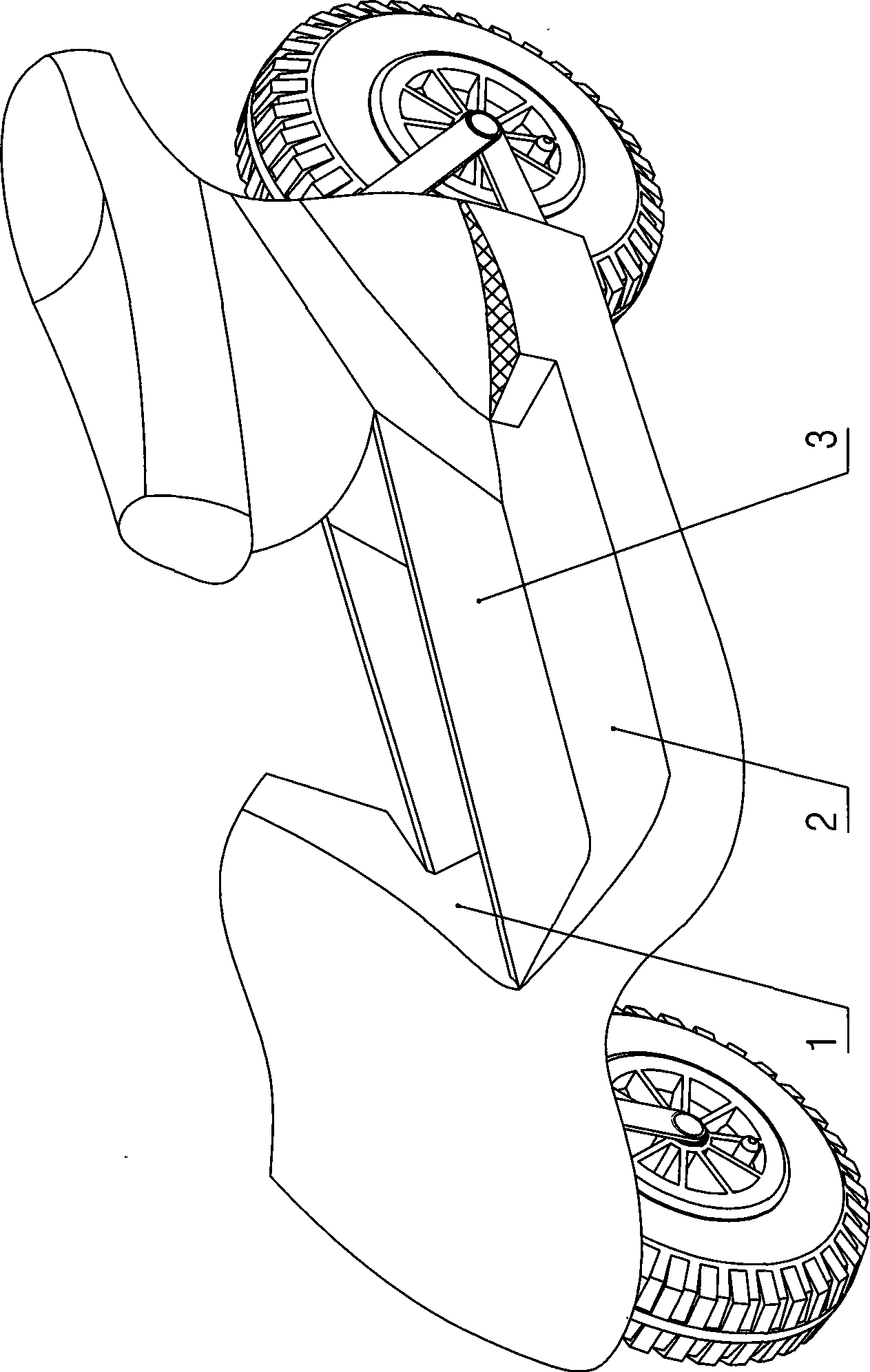
[0025] Example 3:
[0026] Such as Figure 4 As shown, the protective device on the frame of the present invention includes: a pedal 2 arranged in the middle of the frame 1, a protective plate 3 is provided on both sides of the pedal 2, two protective plates 3 and the frame A protective room is formed between 1, and a cover plate 4 is provided on the top of the two protective plates 3 to make the protective room a closed box structure. One side of the cover plate 4 is movably arranged with one of the protective plates 4 through a hinge 5 (also called a hinge) to form a top-opening door. Similarly, one side of the protective plate 3 can also be movably arranged with the frame 1 to form a side door. In addition, in practical applications, a foot pad for foot rest or a seat pad for sitting on the cover plate 4 can also be provided.
[0027] The protective plate 3 in the above embodiment can also be set to Figure 5 The structure shown includes: a retractable protective plate body 32 and
PUM
 Abstract
Description
Claims
Application Information
 - R&D Engineer
- R&D Manager
- IP Professional
- Industry Leading Data Capabilities
- Powerful AI technology
- Patent DNA Extraction
Browse by: Latest US Patents, China's latest patents, Technical Efficacy Thesaurus, Application Domain, Technology Topic.
© 2024 PatSnap. All rights reserved.Legal|Privacy policy|Modern Slavery Act Transparency Statement|Sitemap