Oxide thin film
Inactive Publication Date: 2001-09-25
TDK CORPARATION +1
View PDF4 Cites 4023 Cited by
- Summary
- Abstract
- Description
- Claims
- Application Information
AI Technical Summary
Problems solved by technology
However, since prior art transparent conductive oxides are all of n type and no transparent conductive oxides of p type are available, it is difficult to form a p-n junction solely from transparent conductive oxides.
This suggests that even if a hole is successfully created by any suitable means in order to provide a p-type transparent conductive thin film, the hole is localized on the oxygen ion and has a deep level that cannot be ionized at room temperature, failing to prov
Method used
View moreImage
Smart ImageViewing Examples

Examples
 PUM
| Property | Measurement | Unit |
|---|---|---|
| Thickness | aaaaa | aaaaa |
| Energy | aaaaa | aaaaa |
| Surface roughness | aaaaa | aaaaa |
Abstract
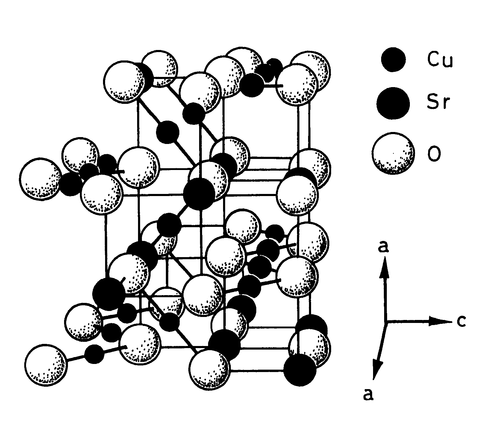
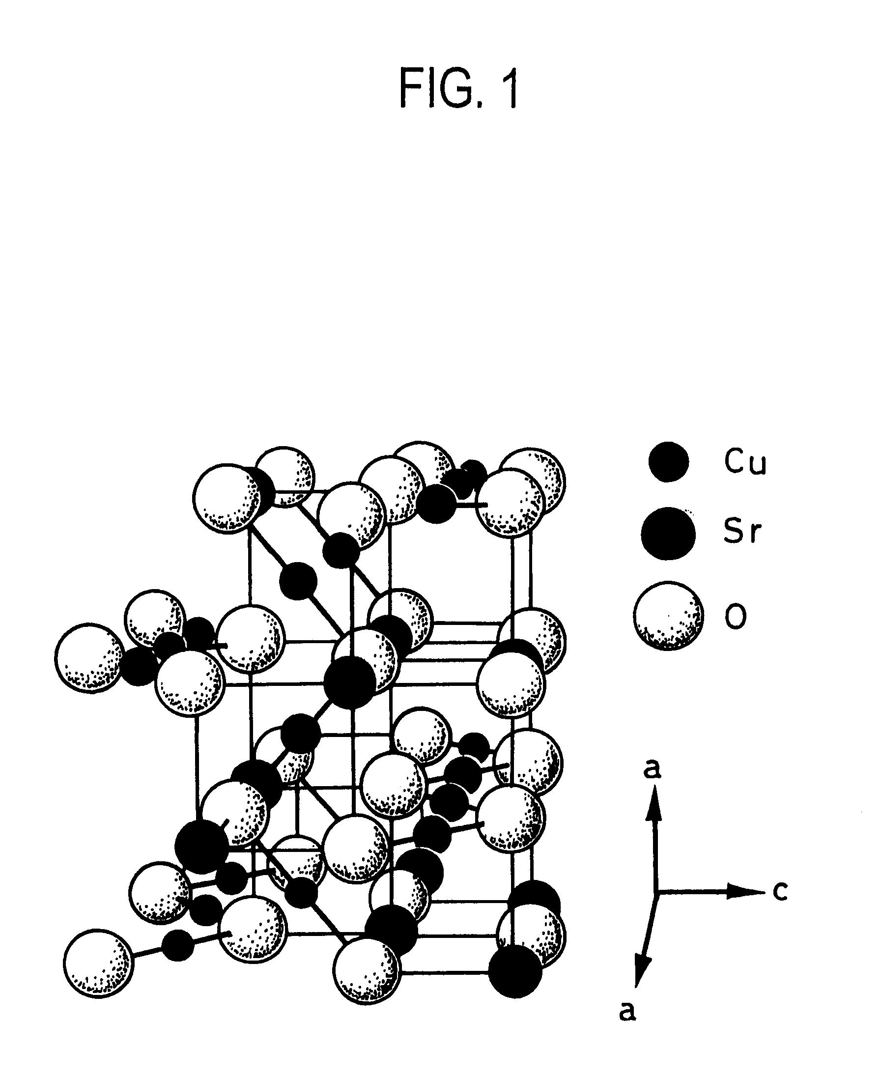
An object of the invention is to provide an oxide thin film which exhibits a widegap or transparency and p-type conductivity although it has heretofore been very difficult to form. The oxide thin film formed on a substrate contains copper oxide and strontium oxide as a main component and exhibits p-type conductivity at a bandgap of at least 2 eV.
Description
Login to view more Claims
Login to view more Application Information
Patent Timeline
 Owner TDK CORPARATION
- R&D Engineer
- R&D Manager
- IP Professional
Why Eureka
- Industry Leading Data Capabilities
- Powerful AI technology
- Patent DNA Extraction
Try Eureka
Browse by: Latest US Patents, China's latest patents, Technical Efficacy Thesaurus, Application Domain, Technology Topic.
© 2024 PatSnap. All rights reserved.Legal|Privacy policy|Modern Slavery Act Transparency Statement|Sitemap