Inverter and overload protection method

A power conversion device and electric power technology, which is applied in the direction of output power conversion device, emergency protection circuit device, electrical components, etc., can solve the problems of sudden stop of the motor, damage to production efficiency, etc., and achieve the effect of preventing sudden stop

Active Publication Date: 2012-10-17
HITACHI IND EQUIP SYST CO LTD
View PDF5 Cites 8 Cited by
  • Summary
  • Abstract
  • Description
  • Claims
  • Application Information

AI Technical Summary

Problems solved by technology

[0004] Therefore, when the time interval between the first overload and the second overload in the above-mentioned AC motor is long (the above-mentioned 10 minutes), at the time of light load between the first overload and the second overload, although the above-mentioned AC The motor actually cools down due to heat dissipation, and the temperature drops, but the above-me

Method used


Image

  • Inverter and overload protection method
  • Inverter and overload protection method
  • Inverter and overload protection method

Examples


Embodiment Construction

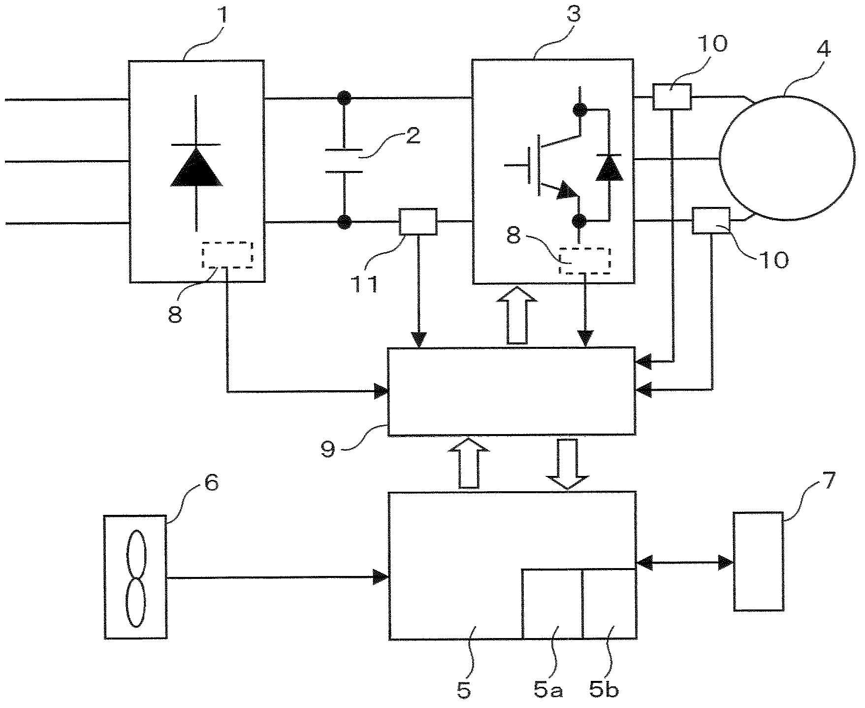
[0030] figure 1 is a configuration diagram of the main circuit of the power conversion device according to the embodiment of the present invention. 1 is a rectifier that rectifies commercial AC power and converts it to DC power; An AC motor that controls the speed of AC power at a given frequency. 6 is a cooling fan for cooling the power modules in the above-mentioned rectifier and inverter.

[0031] 7 is a digital control panel capable of setting, changing, abnormal state and monitoring and displaying various control data of the power conversion device. 8 is a temperature detector provided inside the power semiconductor modules of the rectifier 1 and the inverter 3 . 9 is a drive circuit for driving the switching elements of the inverter 3, 10 is a current detector, and 11 is a resistor for detecting current in the DC circuit. For example, the line current of the AC motor 4 is detected by the current detector 10, and the overload state of the AC motor can be determined from


PUM


Abstract

Inverters have built-in electron thermal time limit characteristics with the aim of protecting against the overload of alternating-current motors, and there is a need for protection that takes into account the actual temperature of the motor. Provided are an inverter and overload protection method having accurate electron thermal energy time limit characteristics that take the actual increases and decreases in temperature of a motor into consideration during overload and under normal load. The power converter is provided with: a rectifier that converts an alternating current into a direct current; a power inverter that converts a direct current into alternating-current electric power with a variable voltage and variable frequency; an alternating-current motor, the speed of which is controlled by the alternating-current power; a current detector that detects the current of the alternating-current motor; and a control unit that controls each of the aforementioned parts according to the current detected by the current detector. The control unit comprises: an adder/subtracter that adds electronically when the alternating-current motor is operating in overload, and when the alternating-current motor is not operating in overload, subtracts a weighting commensurate with the square time product of the current detected by the current detector during overload, from the cumulative value obtained by the addition during overload; and an electronic thermal heat timing unit that stops the alternating-current motor in the event of an overload operation, based on the integrated value in the adder/subtracter and preset electron thermal heat time limit characteristics.

Description


Claims


Application Information

Patent Timeline
Owner HITACHI IND EQUIP SYST CO LTD
Why Eureka
Try Eureka