Polymer dispersed liquid crystal thin box micro-displacement sensor and measuring method thereof

A micro-displacement sensor and displacement technology, applied in the field of displacement sensors, can solve the problems of adding unstable factors, interference, and liquid crystal dynamic scattering to the sensor, and achieve simple and accurate measurement, convenient production, and avoiding interference.

Inactive Publication Date: 2013-09-11
INST OF SEMICONDUCTORS - CHINESE ACAD OF SCI
View PDF4 Cites 0 Cited by
  • Summary
  • Abstract
  • Description
  • Claims
  • Application Information

AI Technical Summary

Benefits of technology

This technology simplifies its production process while also being able to accurately measure tiny movements without requiring an external source like electrical current or voltage changes for better accuracy. It offers technical benefits that are useful across various industries including medical devices (medication delivery systems), biomedical applications, electronic components used in industrial processes, etc., which require precise measurements over very short distances.

Problems solved by technology

Technics: In this patented method for detecting tiny movements caused by liquids containing positive or negative molecules, it suggests that there can be two types of interaction called dispersion and interference effects - these interactions lead to changes in how much energy passes through the material when compressed (the type used) causing variations in its refractive index. These techniques involve applying voltages across different parts of the device such as electrodes, conductor lines, etc., resulting in measurements over several hours.

Method used


Image

  • Polymer dispersed liquid crystal thin box micro-displacement sensor and measuring method thereof
  • Polymer dispersed liquid crystal thin box micro-displacement sensor and measuring method thereof
  • Polymer dispersed liquid crystal thin box micro-displacement sensor and measuring method thereof

Examples


Embodiment Construction

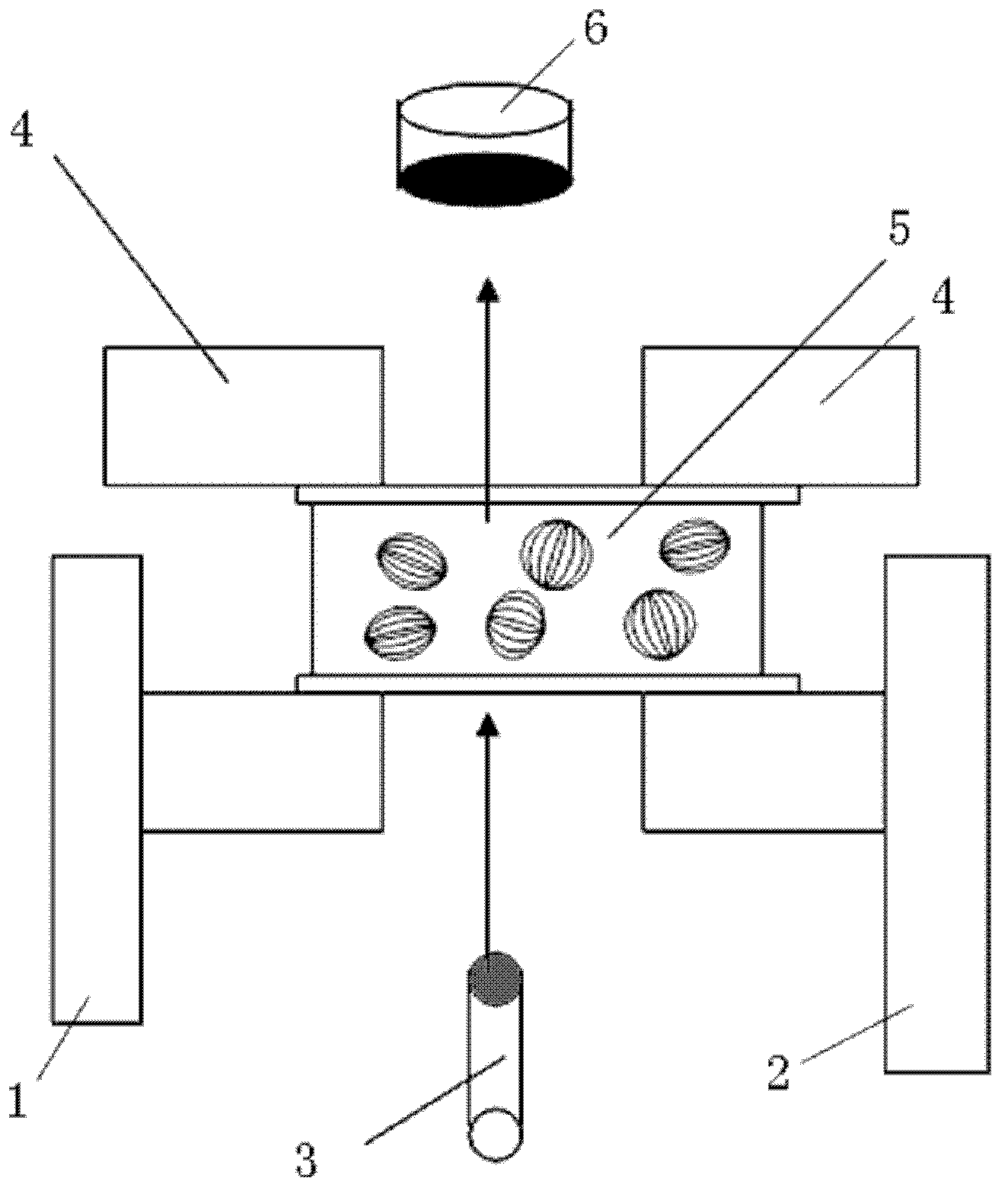
[0021] The present invention achieves micro-displacement sensing measurements by using polymer dispersed liquid crystal (PDLC) thin cells. Specifically, the micro-displacement sensor of the present invention includes a thin PDLC cell, a laser that provides a light source incident on the PDLC thin cell, and a photodetector that receives light transmitted through the PDLC thin cell.

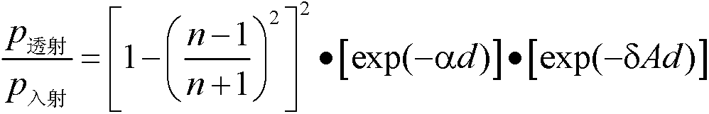
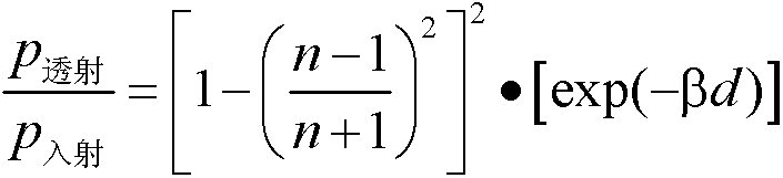
[0022] The principle of the present invention is based on the calendering effect of the PDLC thin cell, that is, its light transmittance changes with pressure. Therefore, the scattering loss per unit length of the PDLC thin cell can be found through the relationship between the incident light and the transmitted light of the PDLC thin cell when the measured object is not placed or when the measured object is placed, and then, by measuring the measured object The relationship between the incident light and the transmitted light can be used to measure the thickness of the PDLC thin cell, and the displac


PUM

PropertyMeasurementUnit
Thicknessaaaaaaaaaa
Wavelengthaaaaaaaaaa

Abstract

The invention discloses a PDLC (polymer dispersed liquid crystal) thin box micro-displacement sensor comprising a PDLC thin box, a laser device, a clamping device and a laser detector. The thin box is provided with a first contact face and a second contact face which are parallel to each other. The laser device generates laser irradiating to the thin box. The clamping device supports and fixes with the first contact face of the thin box in a manner of balanced force. The laser detector receives and detects laser penetrating the thin box. An object to be detected contacts with the second contact face of the thin box; when the object to be detected displaces, the second contact face of the thin box is enabled to displace with the object to be detected, the thickness of the thin box changes accordingly, and the amount, detected by the laser detector, of the laser penetrating the thin box changes. The PDLC thin box micro-displacement sensor is convenient to produce, power addition is omitted, the electric field is prevented from changing with changes of the thickness of the thin box to produce influences, cost of an ITO (indium tin oxides) layer is saved, and cost of a micro-displacement sensor system is reduced effectively.

Description


Claims


Application Information

Patent Timeline
Owner INST OF SEMICONDUCTORS - CHINESE ACAD OF SCI
Why Eureka
Try Eureka