Equalizing Device, Equalizing Method And Receiving Device
A technology of equalization device and equalization method, which is applied to the shaping network and baseband system components in the transmitter/receiver, and can solve the problems of estimating autocorrelation noise, reducing the accuracy of transmission path estimation, and being unable to correctly correct the distortion of received signals, etc. , to achieve the effect of correcting distortion
- Summary
- Abstract
- Description
- Claims
- Application Information
AI Technical Summary
Benefits of technology
Problems solved by technology
Method used
Image

Examples
Embodiment approach 1
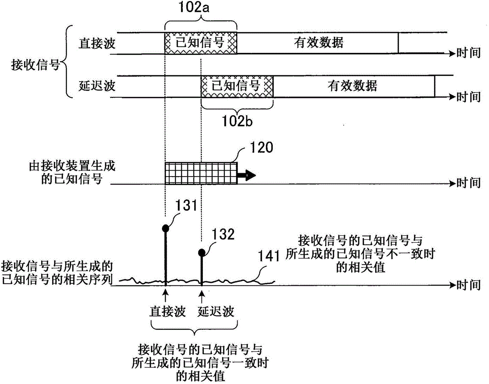
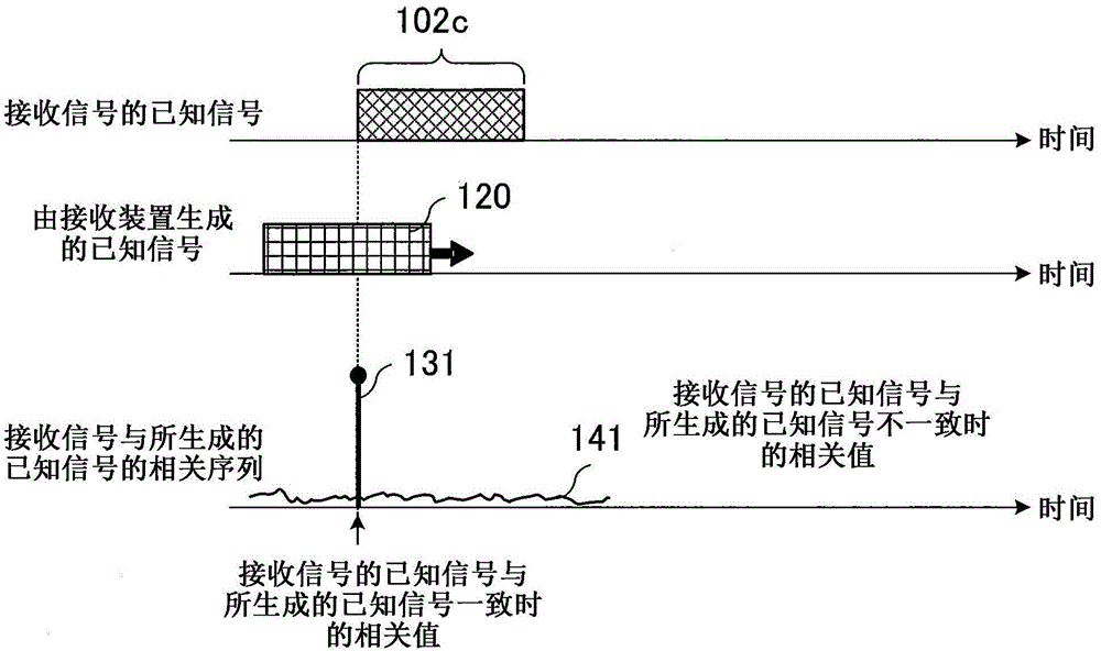
[0035] First, the principle of the present invention will be explained. In Embodiment 1, the premise is that the noise included in the correlation sequence (correlation result) c showing the correlation between the received signal received by the equalizer and the known signal provided (generated) by the equalizer The noise W based on the correlation with the valid data of the received signal within data , and the noise W based on the correlation with Gaussian noise noise is sufficiently suppressed by the smoothing process described using Equation 2 above. In this case, the matrix expression showing the relationship between the correlation sequence c and the delay profile h that is the channel estimation result is the following equation 3, where the correlation sequence c shows the difference between the received signal received by the equalizer and the delay profile h provided by the equalizer. Correlations between known signals.
[0036] c=Wh (Formula 3)
[0037] Formula 3
Embodiment approach 2
[0063] According to Embodiment 1, even in an environment where there are many small incoming waves, it is possible to estimate the transmission path characteristics with high accuracy, but it is necessary to perform an autocorrelation noise suppressing unit 14 to perform M×1 The column vector of , multiplied by the pre-computed M×M inverse matrix G -1 , so the calculation amount is relatively large. Therefore, in Embodiment 2, an equalization device 2 capable of improving the accuracy of channel estimation and reducing the amount of calculation as in Embodiment 1 will be described.
[0064] Figure 8 It is a block diagram schematically showing the configuration of the equalizer 2 according to the second embodiment. Figure 8 in, for Figure 7 The structural elements shown are the same as or corresponding to the structural elements, marked with Figure 7 The numbers shown are the same as those shown. Such as Figure 8 As shown, in the equalizer 2 of the second embodiment, th
Embodiment approach 3
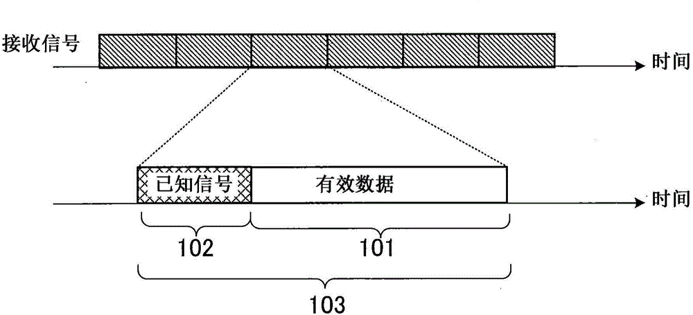
[0083] Hereinafter, an equalization method according to Embodiment 3 will be described. Figure 10 It is a flowchart showing the equalization method of Embodiment 3. The equalization method of Embodiment 3 corresponds to the processing performed by the equalization device 1 of Embodiment 1. Therefore, in Embodiment 3, Embodiment 1 and the diagrams used in the description of Embodiment 1 are also referred to. The equalization method according to Embodiment 3 is, for example, an equalization method for correcting distortion of a received signal R0 in which a transmission unit is a transmission symbol composed of effective data including information to be transmitted and a known signal. This equalization method has: a known signal providing step ST1 which provides a known signal pn[k]; and a correlation calculation step ST2 which generates a correlation sequence c showing the difference between the received signal R0 and the provided known signal relevance. The equalization metho
PUM
 Abstract
Description
Claims
Application Information
 - R&D Engineer
- R&D Manager
- IP Professional
- Industry Leading Data Capabilities
- Powerful AI technology
- Patent DNA Extraction
Browse by: Latest US Patents, China's latest patents, Technical Efficacy Thesaurus, Application Domain, Technology Topic.
© 2024 PatSnap. All rights reserved.Legal|Privacy policy|Modern Slavery Act Transparency Statement|Sitemap