Projector
A projector and sliding mechanism technology, applied in the field of projectors, can solve problems such as picture distortion, uneven color, uneven brightness, etc., and achieve the effect of uniform brightness and color, and small picture distortion
- Summary
- Abstract
- Description
- Claims
- Application Information
AI Technical Summary
Benefits of technology
Problems solved by technology
Method used
Image

Examples
Embodiment 1
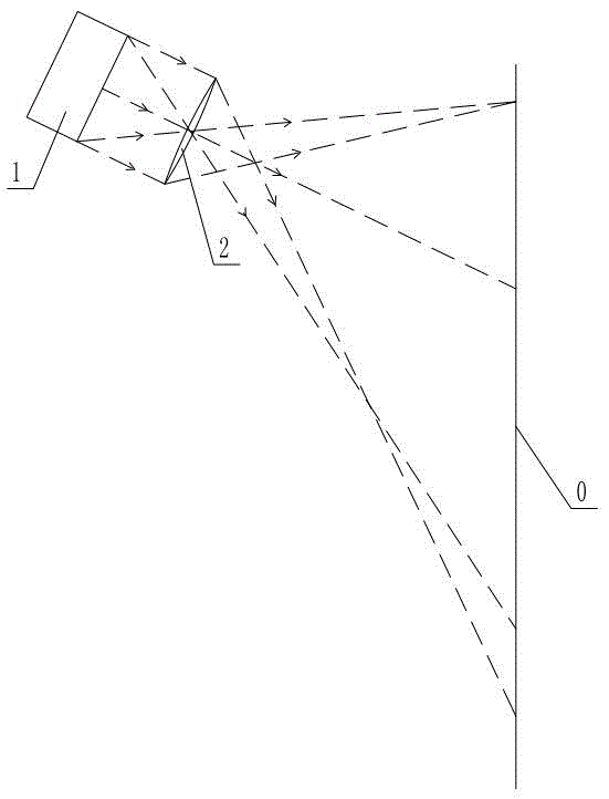
[0030] As shown in the figure, the projector includes a spatial light modulation device 1 and a lens 2 arranged in a casing 7, the axis line of the outer edge of the lens passes through the geometric center 4 of the area where the spatial light modulation device displays effective pixels, and the lens 2 is Taking a straight line parallel to the axis line outside the axis line of the rotationally symmetrical lens 11 as the axis, and taking another straight line parallel to the axis line of the rotationally symmetrical lens 11 as the rotation line, intercepting a part of the rotationally symmetrical lens 11, The structure of the lens 2 is non-rotationally symmetrical, and its optical center 3 is outside the axis line of the outer edge of the lens 2, and the optical center 3 is also parallel to the lens through the geometric center 4 of the effective pixel area displayed by the spatial light modulation device 1. 2 outside the straight line of the axis line.
[0031]In this solution,
Embodiment 2
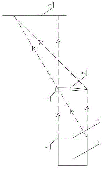
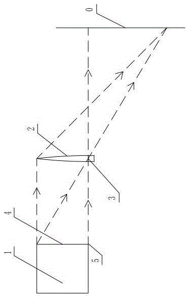
[0035] As shown in the figure, this projector includes a spatial light modulation device 1 and a lens 2 arranged in the casing 7 like the first embodiment, and the axis line of the outer edge of the lens passes through the spatial light modulation device to display the geometry of the area of effective pixels. Center 4, lens 2 is based on a straight line parallel to the axis line outside the axis line of the rotationally symmetrical lens 11, and another straight line parallel to the axis line of the rotationally symmetrical lens 11 is used as the rotation line to intercept the rotationally symmetrical lens 11, the structure of the lens 2 is non-rotationally symmetrical, and its optical center 3 is outside the axis line of the outer edge of the lens 2, and the optical center 3 also passes through the spatial light modulation device 1 to display the geometry of the effective pixel area Center 4 and outside the line parallel to the axis of lens 2.
[0036] The lens 2 is socketed w
Embodiment 3
[0038] Another solution of this patent includes a housing 7, a spatial light modulation device 1 and a lens 2, and also includes a sliding mechanism 15, a large sleeve 8 and a small sleeve 9 with both ends transparent, and the large sleeve 8 is fixedly connected to the housing 7 Together, the small sleeve 9 and the sliding mechanism 15 are affixed together, the large and small sleeves are sleeved together, the small sleeve 9 can rotate relative to the large sleeve 8, the lens 2 is installed on the sliding mechanism 15, and the position of the lens 2 can be adjusted. As the sliding mechanism 15 moves, the lens 2 is rotationally symmetric, and the optical center 3 of the lens 2 can move to a line that passes through the geometric center 4 of the effective pixel area of the spatial light modulation device 1 and is parallel to the axis of the lens 2. Location.
[0039] The projector adopting this scheme, along with the movement of the optical center 3, which direction it deviates,
PUM
 Abstract
Description
Claims
Application Information
 - R&D Engineer
- R&D Manager
- IP Professional
- Industry Leading Data Capabilities
- Powerful AI technology
- Patent DNA Extraction
Browse by: Latest US Patents, China's latest patents, Technical Efficacy Thesaurus, Application Domain, Technology Topic.
© 2024 PatSnap. All rights reserved.Legal|Privacy policy|Modern Slavery Act Transparency Statement|Sitemap