Novel damping suspension composite member

A technology for mounting parts and assemblies, which is applied to power units, vehicle components, jet propulsion units, etc., can solve the problem that the passive end vibration amount is difficult to meet the vibration target requirements of the whole vehicle, and achieves improved NVH performance and improved vibration isolation. rate, the effect of reducing the amount of vibration

Pending Publication Date: 2018-07-17
JIANGXI CHANGHE AUTO
View PDF9 Cites 1 Cited by
  • Summary
  • Abstract
  • Description
  • Claims
  • Application Information

AI Technical Summary

Problems solved by technology

The existing design generally achieves vibration isolation through the rubber bushing inside the suspension assembly, but for the case where the active end of the suspension has a large vibrat

Method used


Image

  • Novel damping suspension composite member
  • Novel damping suspension composite member
  • Novel damping suspension composite member

Examples


Embodiment Construction

[0013] Specific embodiments of the present invention will be described in detail below in conjunction with the accompanying drawings. It should be understood that the orientations or positional relationships indicated by "up", "down", "front", "back", "left", "right", "top", "bottom" etc. are based on the The orientation or positional relationship is only for the convenience of describing the present invention and simplifying the description, but does not indicate or imply that the device or element referred to must have a specific orientation, be constructed and operated in a specific orientation, and therefore cannot be construed as limiting the present invention .

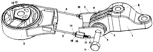
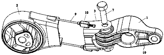
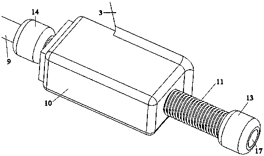
[0014] A novel shock-absorbing suspension assembly includes a suspension assembly and a suspension bracket 1 . The suspension assembly is divided into a first suspension part 2 and a second suspension part 3, the second suspension part 3 is processed with a first connection hole 4, the suspension bracket 1 is proc


PUM


Abstract

The invention discloses a novel damping suspension composite member. The novel damping suspension composite member comprises a suspension assembly and a suspension support. The suspension assembly isdivided into a first suspension piece and a second suspension piece; the second suspension piece is connected with the suspension support; the first suspension piece and the second suspension piece are connected through two damping assemblies; the two damping assemblies are located on the two sides of the first suspension piece and the second suspension piece correspondingly; each damping assemblycomprises a sliding rod, a sliding block and a damping spring; and a fixed connection through hole used for being connected with a vehicle body or an auxiliary vehicle frame is further machined in the first suspension piece. The vibration isolation rate of the suspension composite member is increased, the vibration quantity, transmitted to the vehicle body or the auxiliary vehicle frame through the suspension composite member, of a power assembly is decreased, and the NVH performance of a vehicle is improved.

Description


Claims


Application Information

Patent Timeline
Owner JIANGXI CHANGHE AUTO
Why Eureka
Try Eureka