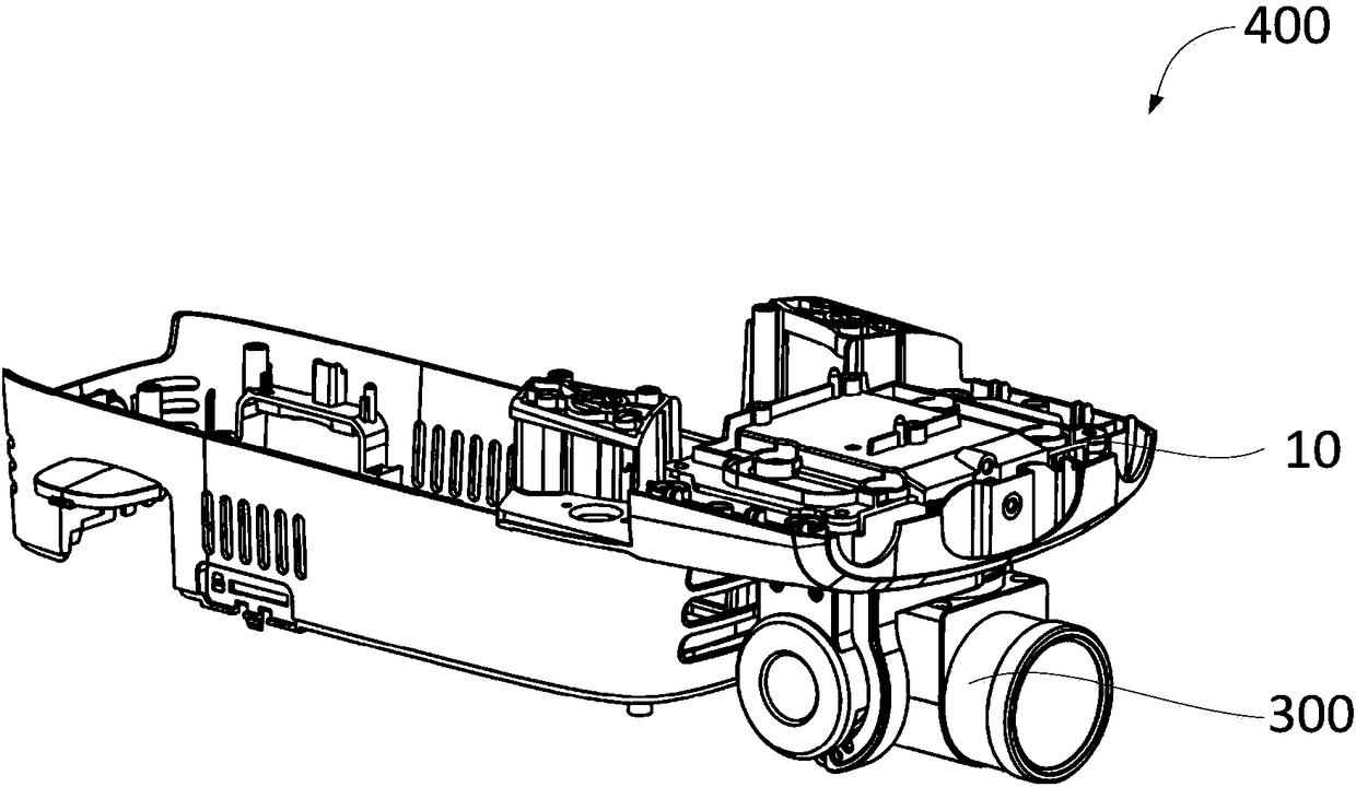
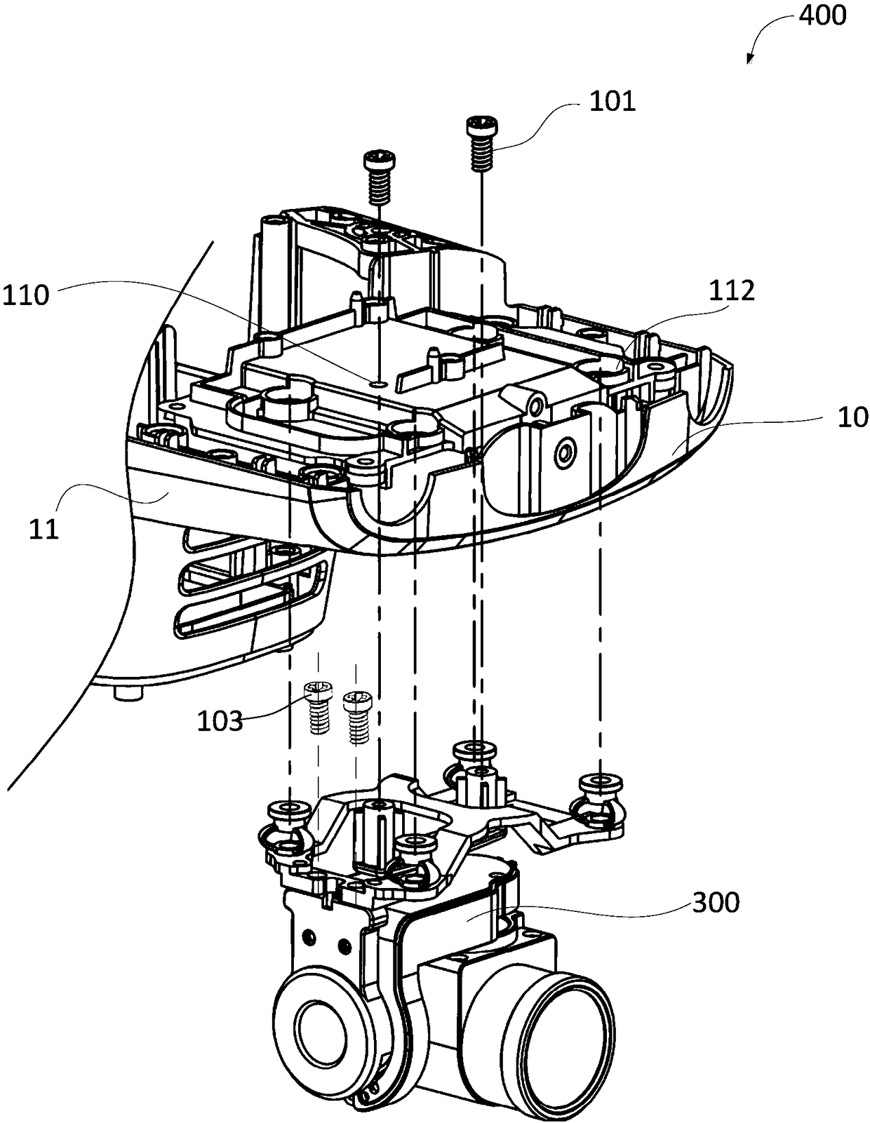
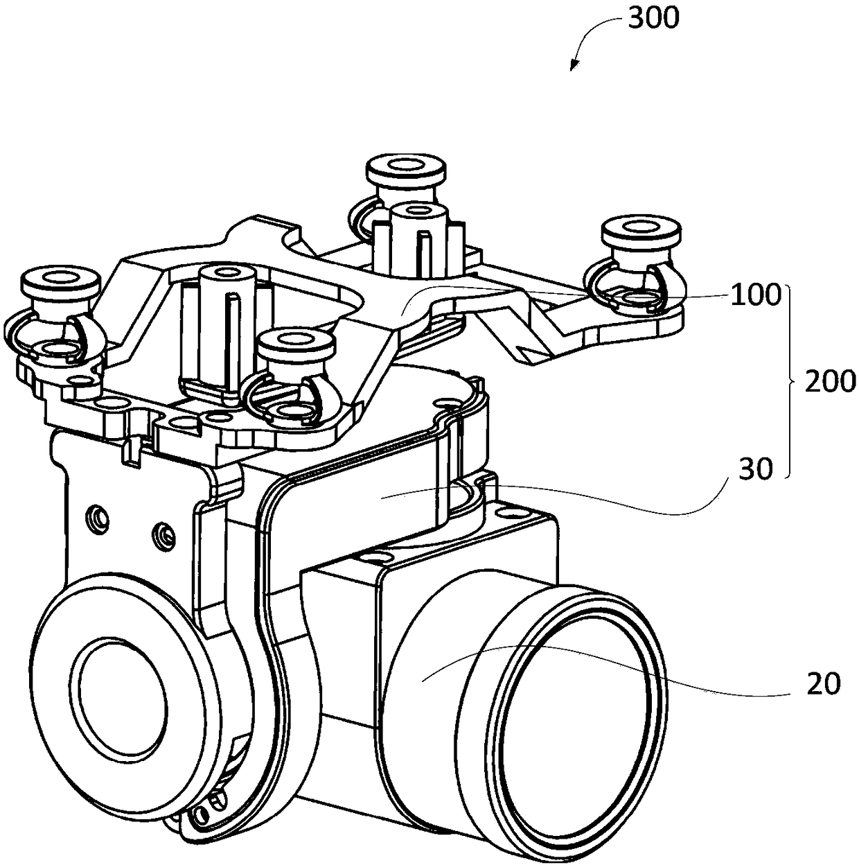
Mounting base, cradle head assembly and unmanned aerial vehicle

A technology of unmanned aerial vehicle and mounting seat, which is applied in the field of aircraft, can solve the problem of unstable load operation of connecting parts, and achieve the effect of stable load operation

Pending Publication Date: 2018-09-28
SHENZHEN AUTEL INTELLIGENT AVIATION TECH CO LTD
View PDF0 Cites 3 Cited by
  • Summary
  • Abstract
  • Description
  • Claims
  • Application Information

AI Technical Summary

Benefits of technology

This new design allows for better control over the movements or positioning of objects during flight without affecting their ability to absorb shocks caused from external sources such as wind gusts or impact waves. By adding this technology into the aircraft's mounting system, it can improve safety measures against these types of disturbances while still providing effective performance under extreme conditions like high altitude flying operations.

Problems solved by technology

This patented technical problem addressed in this patents relates to improving the stability and reliability of connectors for UVs during flight operations due to their unique design featuring compactness, ease of installation, and resistance against damage from external factors such as impact forces.

Method used


Image

  • Mounting base, cradle head assembly and unmanned aerial vehicle
  • Mounting base, cradle head assembly and unmanned aerial vehicle
  • Mounting base, cradle head assembly and unmanned aerial vehicle

Examples


Embodiment Construction

[0031] In order to facilitate the understanding of the present invention, the present invention will be described in more detail below in conjunction with the accompanying drawings and specific embodiments. It should be noted that when an element is said to be "fixed" to another element, it may be directly on the other element, or there may be one or more intervening elements therebetween. When an element is referred to as being "connected to" another element, it can be directly connected to the other element or one or more intervening elements may be present therebetween. The terms "vertical", "horizontal", "left", "right", "inner", "outer" and similar expressions are used in this specification for the purpose of description only.

[0032] Unless otherwise defined, all technical and scientific terms used in this specification have the same meaning as commonly understood by one of ordinary skill in the technical field of the invention. The terminology used in the description of


PUM


Abstract

The invention relates to the technical field of aerial vehicles and discloses a mounting base, a cradle head assembly and an unmanned aerial vehicle. The mounting base comprises a vibration reductiondevice and an anti-separation structure, wherein the vibration reduction device is connected with a cradle head; the vibration reduction device comprises a vibration reduction element connected with the unmanned aerial vehicle; the anti-separation structure is used for mounting the vibration reduction device and the cradle head on the unmanned aerial vehicle; and the anti-separation structure is configured to allow the movement distance between the vibration reduction device and the cradle head at least in the vibration direction of the vibration reduction device to be not less than maximum vibration amplitude of the vibration reduction element. Through adoption of the mode, the anti-separation structure of the mounting base does not interfere a vibration reduction piece so that the load mounted on a connecting piece works stably.

Description


Claims


Application Information

Patent Timeline
Owner SHENZHEN AUTEL INTELLIGENT AVIATION TECH CO LTD
Why Eureka
Try Eureka