Binocular camera depth calibration method, device and system and storage medium

A binocular camera and calibration method technology, which is applied in stereo systems, image data processing, instruments, etc., can solve the problems of low calibration accuracy, slow depth calibration process of binocular cameras, etc., and achieve the effect of accurate depth calibration

Pending Publication Date: 2020-04-07
BEIJING SMARTER EYE TECH CO LTD
View PDF6 Cites 0 Cited by
  • Summary
  • Abstract
  • Description
  • Claims
  • Application Information

AI Technical Summary

Benefits of technology

This patented technology helps improve stereoscopic imagery accuracy when capturing 360 degree images with an eyewear lens attached thereto through different ways such as binoculography or polarization glasses. By measuring how well these methods work for each location within the scene being captured, it can accurately determine where objects are located relative to other cameras during capture. These techniques involve comparing specific areas from both eyes together to find corresponding points that correspond to those parts of interest (such as faces). Based upon their distances and directions, they then adjust focus accordingly. Overall, this technique allows users to see better quality three dimensional scenes even if we don't have them themselves.

Problems solved by technology

This patented technical problem addressed by this patents relates to improving the speed and efficiency of robot or car radar systems' calibrations for binoculators due to their unique characteristics such as being able to accurately measure both distance from objects within range (distance) while also accounting for environmental factors like temperature changes without affecting how well they operate over different temperatures.

Method used


Image

  • Binocular camera depth calibration method, device and system and storage medium
  • Binocular camera depth calibration method, device and system and storage medium
  • Binocular camera depth calibration method, device and system and storage medium

Examples


Embodiment Construction

[0054] The implementation mode of the present invention is illustrated by specific specific examples below, and those who are familiar with this technology can easily understand other advantages and effects of the present invention from the contents disclosed in this description. Obviously, the described embodiments are a part of the present invention. , but not all examples. Based on the embodiments of the present invention, all other embodiments obtained by persons of ordinary skill in the art without making creative efforts belong to the protection scope of the present invention.

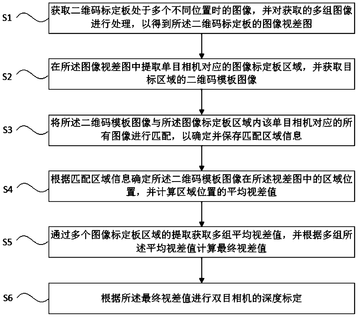
[0055] The binocular camera depth calibration method provided by the present invention realizes fast and accurate depth calibration by using a method of matching the position of a two-dimensional code calibration plate on the basis of binocular visual parallax information. In a specific embodiment, such as figure 1 As shown, the method includes the following steps:

[0056]S1: Acquire the images o


PUM


Abstract

The invention discloses a binocular camera depth calibration method, device and system and a storage medium, and the method comprises the steps: obtaining images of a two-dimensional code calibrationplate at a plurality of different positions, and obtaining an image disparity map of the two-dimensional code calibration plate; obtaining a two-dimensional code template image of the target area; matching the two-dimensional code template image with all images corresponding to the monocular camera in the image calibration plate area so as to determine and store matching area information; determining a region position of the two-dimensional code template image in the disparity map according to the matching region information, and calculating an average disparity value of the region position; obtaining a plurality of groups of average parallax values through the extraction of a plurality of image calibration plate regions, and calculating a final parallax value according to the plurality ofgroups of average parallax values; and performing depth calibration of the binocular camera according to the final parallax value. Based on binocular vision parallax information, rapid and accurate depth calibration is realized by using a method of matching the position of a two-dimensional code calibration plate.

Description


Claims


Application Information

Patent Timeline
Owner BEIJING SMARTER EYE TECH CO LTD
Why Eureka
Try Eureka