A foot shape scanning method and system

A foot shape and foot technology, applied in the field of shoemaking, can solve the problems of unreliable and unstable measurement results, improve accuracy and acquisition speed, reduce the generation of invalid images or invalid data, and integrate accurate alignment Effect

Pending Publication Date: 2020-05-12
意礴数字科技(深圳)有限公司
View PDF7 Cites 2 Cited by
  • Summary
  • Abstract
  • Description
  • Claims
  • Application Information

AI Technical Summary

Problems solved by technology

In actual operation, the shooting angle, light source, and standing scheme may differ from the ideal state, and there is no reliable follow-up scheme to correct the impact o

Method used


Image

  • A foot shape scanning method and system
  • A foot shape scanning method and system
  • A foot shape scanning method and system

Examples


Embodiment Construction

[0022] The preferred embodiments of the present invention will be described in detail below in conjunction with the accompanying drawings, and the reference numerals refer to components and techniques in the present invention, so that the advantages and features of the present invention can be more easily understood in a suitable environment. The following description is the embodiment of the claims of the present invention, and other specific implementations related to the claims that are not explicitly described also belong to the scope of the claims.

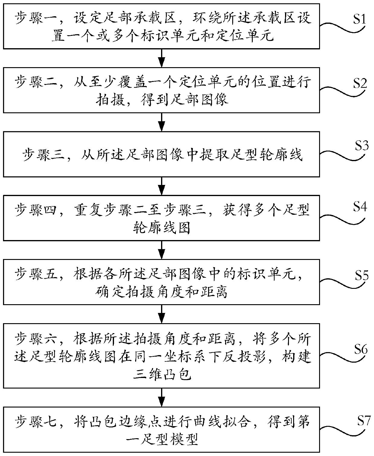
[0023] figure 1 A schematic diagram of the steps of a foot shape scanning method is shown.

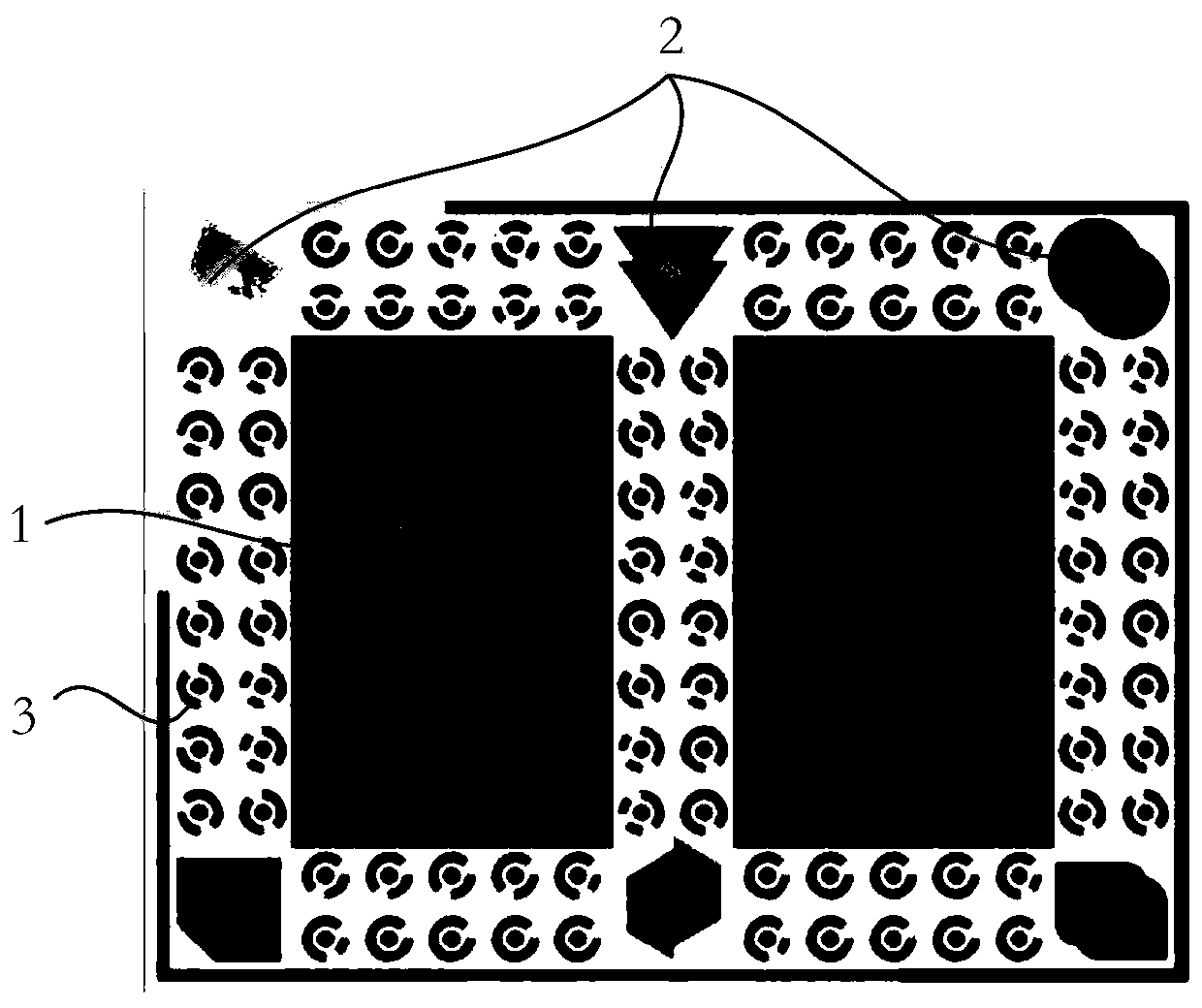
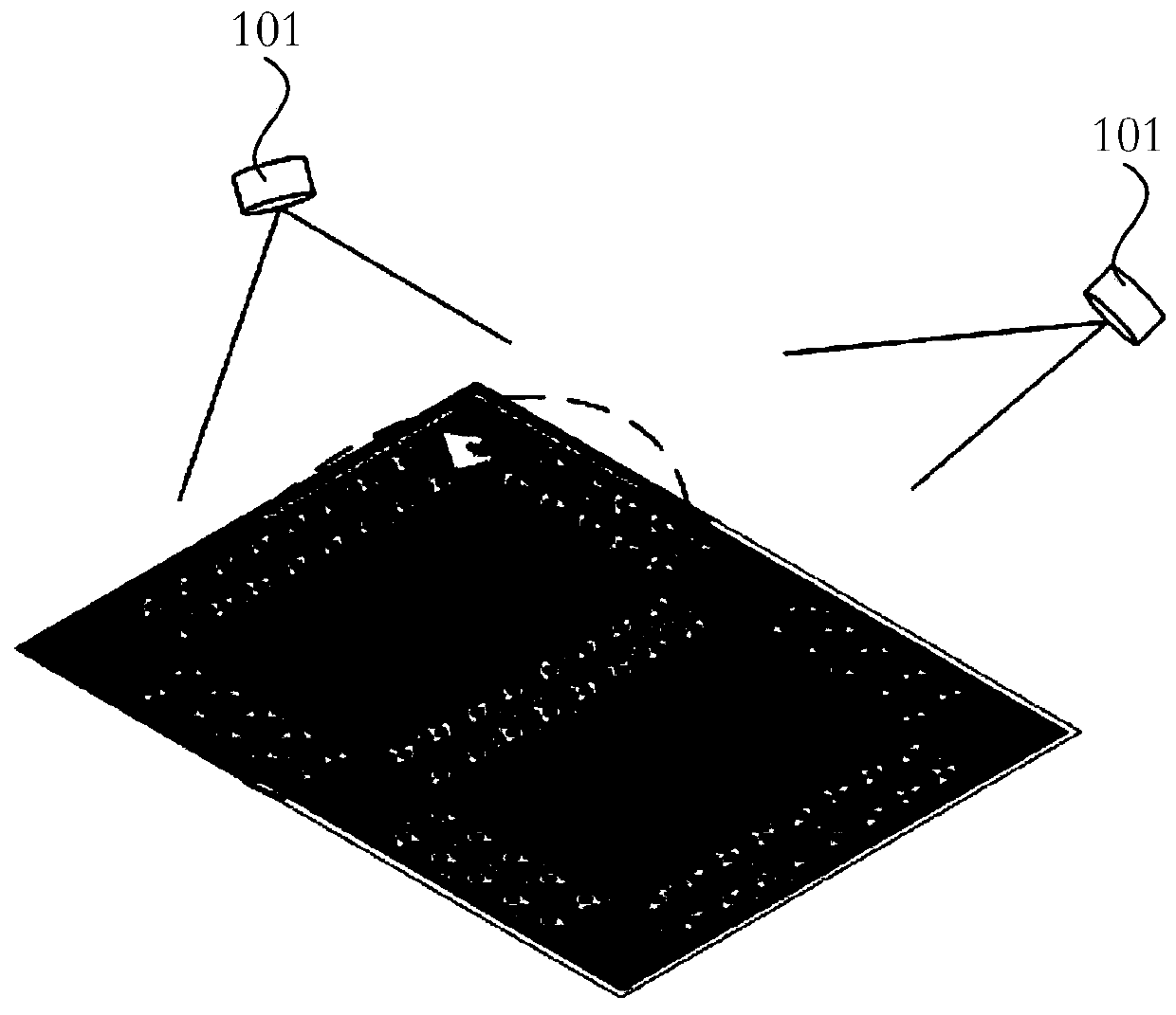
[0024] Such as figure 1 As shown, a method for foot type scanning includes, step one S1, setting the foot bearing area 1, and setting one or more identification units 3 and positioning units 2 around the bearing area 1; step two S2, from at least Covering the position of a positioning unit 2 for shooting to obtain a foot pattern; Step


PUM


Abstract

A foot shape scanning method comprises the steps: S1, setting a foot bearing area, and arranging one or more identification units and positioning units around the bearing area; S2, conducting shootingfrom the position covering at least one positioning unit, and obtaining a foot graph; S3, extracting a foot-shaped contour line from the foot graph; S4, repeating the step 2 and the step 3, and obtaining a plurality of foot shape contour line graphs; S5, determining a shooting angle and a shooting distance according to identification units in the foot graph; S6, according to the shooting angle and the shooting distance, performing back projection on the plurality of foot-shaped contour line graphs under the same coordinate system, and constructing a three-dimensional convex hull; and S7, performing curve fitting on convex hull edge points to obtain a first foot shape model. According to the invention, the generation of invalid images or invalid data is reduced, the integration and alignment of a plurality of foot-shaped contour line graphs are more accurate, and the accuracy and the acquisition speed are remarkably improved.

Description


Claims


Application Information

Patent Timeline
Owner 意礴数字科技(深圳)有限公司
Why Eureka
Try Eureka