Elevator brake follow current control method, device and equipment and medium

A control method and elevator technology, applied in mechanical equipment, transportation and packaging, brake actuators, etc., can solve the problems of reducing the maximum noise of brake release, various brake freewheeling resistances, and shortening the release time, etc., to achieve Meet the needs of use, shorten the release time, and reduce the effect of releasing noise

Active Publication Date: 2020-05-29
HITACHI BUILDING TECH GUANGZHOU CO LTD
View PDF8 Cites 2 Cited by
  • Summary
  • Abstract
  • Description
  • Claims
  • Application Information

AI Technical Summary

Problems solved by technology

It can be seen that according to the traditional brake control method, no matter whether it is normal braking or emergency stop of the elevator, the maintenance current at the initial moment of brake release and the freewheeling resistance during the brake release process are unchanged, which directly leads to the normal and emergency stop of the brake. There is no difference in the release time, that is, the traditional brake control method has the problem of not being able to reduce the maximum noise of the brake release and shorten the release time, resulting in the difficulty of matching the brake and the use of various brake freewheeling resistors.

Method used


Image

  • Elevator brake follow current control method, device and equipment and medium
  • Elevator brake follow current control method, device and equipment and medium
  • Elevator brake follow current control method, device and equipment and medium

Examples


Example Embodiment

[0033] The present invention will be further described in detail below with reference to the drawings and embodiments. It can be understood that the specific embodiments described here are only used to explain the present invention, but not to limit the present invention. In addition, it should be noted that, for ease of description, the drawings only show a part but not all of the structure related to the present invention.

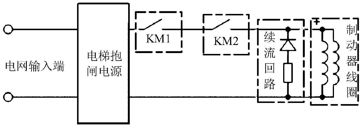
[0034] In the specific implementation, different brakes are different in terms of mechanical structure, working current, coil inductance and coil resistance. Each brake power supply needs to match different freewheeling resistance to meet the requirements for freewheeling of the brake coil. . Without changing the mechanical structure of the elevator brake, reducing the brake release noise and reducing the release time are contradictory. Specifically, in order to reduce the release noise of the brake, it is necessary to reduce the resistance of the freewheeli


PUM


Abstract

The embodiment of the invention discloses an elevator brake follow current control method, device and equipment and a medium, and relates to the technical field of elevators. The elevator brake followcurrent control method comprises the steps that the elevator state and a control instruction corresponding to the elevator state are determined; and according to a control signal corresponding to thecontrol instruction, the brake coil current is subjected to chopping control till the brake coil current is reduced to the current threshold value corresponding to the elevator state. The brake coilcurrent is controlled through the control signal corresponding to the control instruction, the purpose of actively adjusting the electromagnetic force is achieved, accordingly, the brake releasing time and noise can be changed, accordingly, releasing noise reduction and releasing time shortening can be effectively considered, and the usage requirements of different brakes are met.

Description


Claims


Application Information

Patent Timeline
Owner HITACHI BUILDING TECH GUANGZHOU CO LTD
Why Eureka
Try Eureka