Setting method of nuclear level indicator for pressure vessel

A pressure vessel and material level gauge technology, which is applied in the field of nuclear material level gauges for pressure vessels, can solve the problems of difficulty in relieving local peak stress at the outer edge of openings, difficulty in tightly fitting welded pipes, and strong radiation safety risks, etc. Achieve the effect of simple and reliable setup, simple manufacturing, and improved fatigue and creep failure resistance.

Pending Publication Date: 2021-06-08
CHINA PETROLEUM & CHEM CORP +2
View PDF0 Cites 0 Cited by
  • Summary
  • Abstract
  • Description
  • Claims
  • Application Information

AI Technical Summary

Problems solved by technology

[0004] In order to ensure the bearing capacity and anti-fatigue and anti-creep performance of the non-penetrating opening, the engineering design usually adopts to reduce the opening depth to ensure that the shell at the opening has a large residual wall thickness, but in order to ensure a certain For penetrability, it is necessary to increase the dose of the emission source of the nuclear level gauge. This solution is not only economical, but also brings strong radiation safety risks.
Another solution is to weld the reinforced short pipe outside the opening, but there are the following problems: it is difficult to achieve full penetration connection between the short pipe and the outer wall of the cylinder, and it is difficult to achieve a close fit between the inner side of the welded pipe and the outer edge of the opening, so its The strengthening effect is limited, and the local peak stress on the outer edge of the opening is difficult to be relieved

Method used


Image

  • Setting method of nuclear level indicator for pressure vessel
  • Setting method of nuclear level indicator for pressure vessel

Examples


Example Embodiment

[0031] The present invention will be further described below with reference to the accompanying drawings.

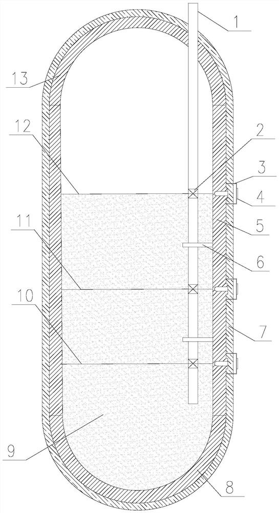
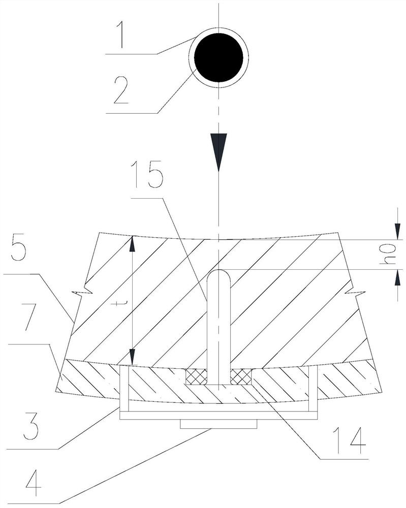
[0032] Combine figure 1 with figure 2 Nuclear material setting method for the pressure vessel provided by the present invention includes the following steps:

[0033] 1) Determine the mounting position on the pressure vessel in the pressure vessel according to the minimum operating position 10 of the material 9 in the pressure vessel.

[0034] 2) Determining the installation sequence of each component of the nuclear material measure according to the mounting position of the nuclear material discharge site:

[0035] A. Install the built-in nuclear source sleeve: Built-in nuclear source sleeve 1 generally insert the pressure vessel cylinder 5 from the pressure vessel body 5, close to the bottom of the pressure vessel cylinder 5, in ensuring built-in nuclear source sleeve 1 and pressure vessel Under the premise of the upper head 13 opening, the built-in nuclear source sleeve 1 is


PUM

PropertyMeasurementUnit
Thicknessaaaaaaaaaa
Diameteraaaaaaaaaa

Abstract

The invention discloses a method for setting a nuclear level indicator for a pressure vessel, which comprises the following steps of: 1) determining the mounting position of the nuclear level indicator on the pressure vessel according to an operation level in the pressure vessel; 2) according to the mounting position of the nuclear level indicator, determining the installation sequence of the nuclear level indicator as follows: a, the built-in nuclear source sleeve is installed; b, setting a nuclear emission source; c, surfacing the annular boss; d, a non-penetrating hole is machined; and e, installing a nuclear ray receiver. According to the method for setting the nuclear level gauge, the depth of the non-penetrating open pore can be greatly improved, so that the penetrability of rays of the nuclear level gauge is improved, the dosage of a nuclear source is reduced, and the economic cost and additional radiation risk of the nuclear level gauge are reduced.

Description


Claims


Application Information

Patent Timeline
Owner CHINA PETROLEUM & CHEM CORP
Why Eureka
Try Eureka