Cable fault detector and using method

A cable fault detector technology, applied in the direction of fault location, fault detection according to conductor type, information technology support system, etc., can solve the problem of inconvenient fault detection, achieve low cost, high reliability, and simple implementation

Pending Publication Date: 2021-10-08
国网山东省电力公司曲阜市供电公司 +2
View PDF0 Cites 0 Cited by
  • Summary
  • Abstract
  • Description
  • Claims
  • Application Information

AI Technical Summary

Benefits of technology

The present inventors have developed an improved device for identifying if there are any cables or wires going wrong during operation without having them gone bad altogether. This helps maintaining important assets more efficiently while also being able to identify potential issues quickly with minimal effort compared to traditional systems like power lines.

Problems solved by technology

This patented technical solution involves developing a simulation model called Fault Line Selection System (FLS) based upon multiple factors such as temperature and humidity levels during each phase of electrical transmission lines' normal operations. By testing this simulation model against data from previous phases, we aimed at identifying potential causes of failures within specific areas of the grid. These identified issues could lead to more efficient use of resources and reduced downtime caused by poorly functioning equipment.

Method used


Image

  • Cable fault detector and using method
  • Cable fault detector and using method

Examples


Embodiment Construction

[0027] The following will clearly and completely describe the technical solutions in the embodiments of the present invention with reference to the accompanying drawings in the embodiments of the present invention. Obviously, the described embodiments are only some of the embodiments of the present invention, not all of them.

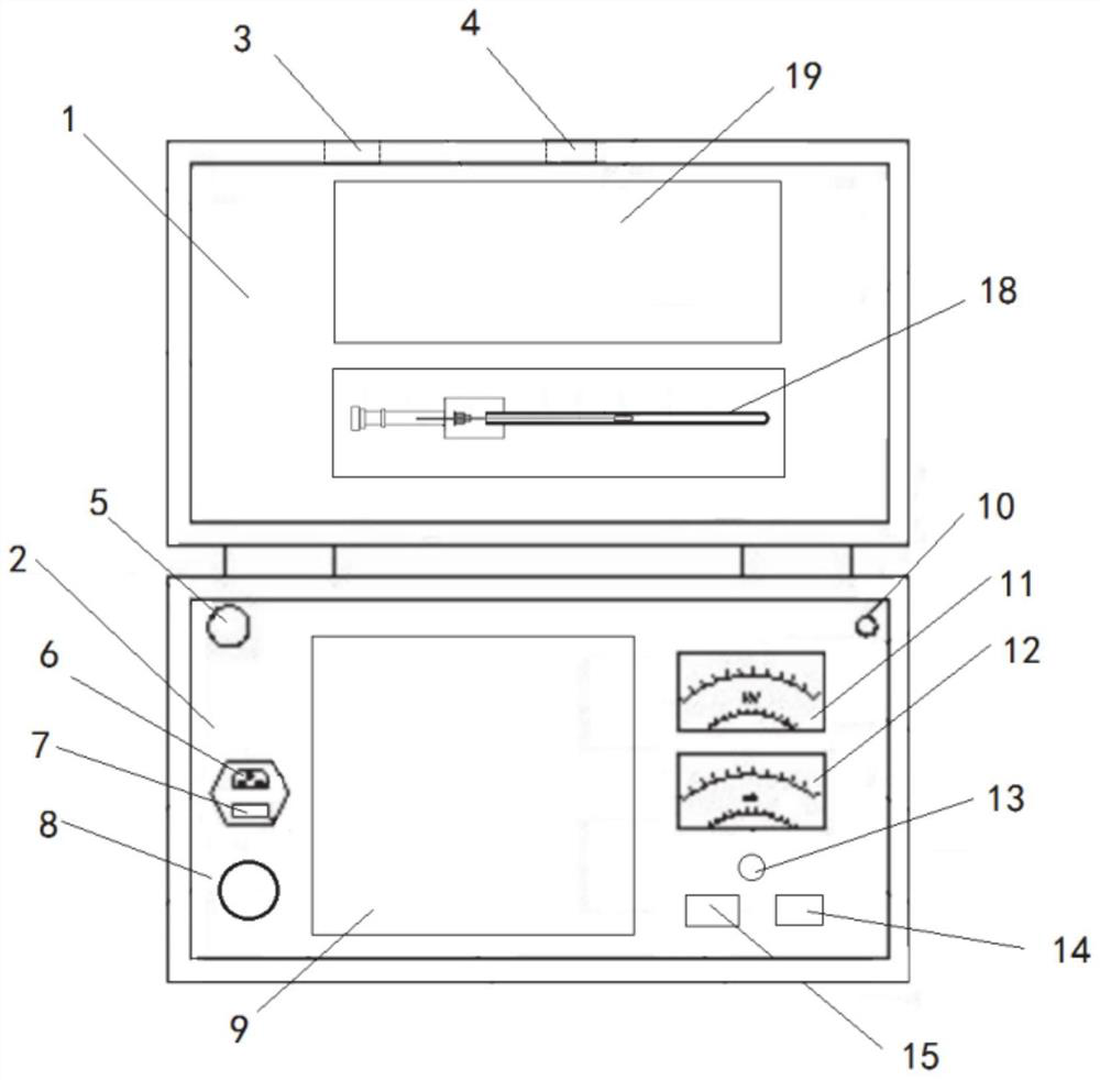
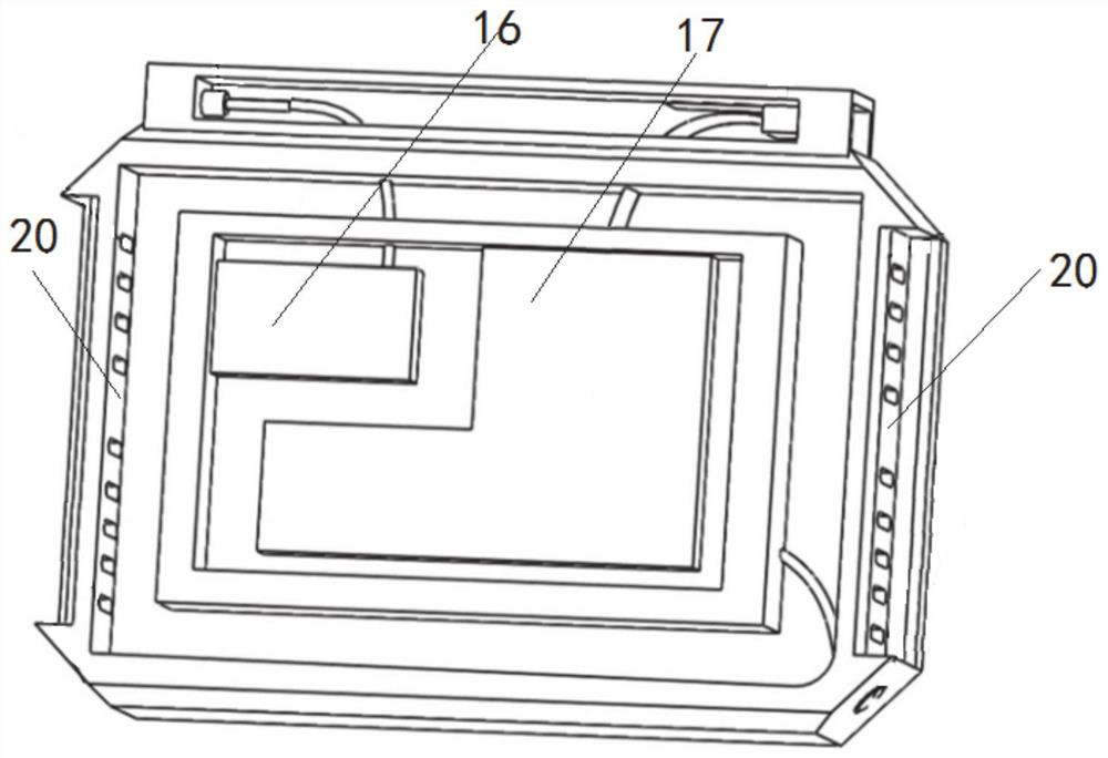
[0028] refer to Figure 1-2 , a cable fault detector, comprising a case cover 1 and a case body 2, the case cover 1 is installed on one side of the case body 2 for rotation, and the side of the case cover 1 is respectively provided with a USB transfer interface 3 and a probe jack 4; The box body 2 is provided with a high-voltage output interface 5, a power interface 6, a power switch 7, and a cooling hole 20; the power interface 6 is used to connect with the power supply, the transformer is used to convert 220V voltage into high-voltage transmission, and the power switch 7 is used to control Circuit breaks.

[0029] A transformer and a touch-operable disp


PUM


Abstract

The invention relates to the technical field of fault detection, in particular to a cable fault detector and a using method, the cable fault detector comprises a box cover and a box body, the box cover is rotatably mounted on one side of the outer part of the box body, and a probe jack and a USB adapter are respectively arranged on two sides of the box cover; the box body is provided with a high-voltage output interface, a power interface, a power switch and heat dissipation holes; a transformer and a touch-operated display screen are arranged in the box body, the low-voltage end of the transformer is connected with the power interface through a wire, the high-voltage end of the transformer is connected with the high-voltage output interface through a wire, and the power switch is connected with the transformer in series; a touch-operated display screen is embedded in the front surface of the box body, the back surface of the touch-operated display screen is respectively connected with a detection processing module and a control module, and the detection processing module and the control module are fixed in an inner slot of the box body; and the fault position can be accurately positioned.

Description


Claims


Application Information

Patent Timeline
Owner 国网山东省电力公司曲阜市供电公司
Why Eureka
Try Eureka