Switched reluctance motor torque control method and modular power converter thereof

A technology of switched reluctance motor and power converter, which is applied in the direction of AC motor control, conversion of AC power input to DC power output, and output power conversion devices, etc. Device burden and other issues, to avoid the effect of free response

Active Publication Date: 2022-06-07
NORTHWESTERN POLYTECHNICAL UNIV
View PDF9 Cites 0 Cited by
  • Summary
  • Abstract
  • Description
  • Claims
  • Application Information

AI Technical Summary

Benefits of technology

This patented technology allows for better performance when controlling electric machines by generating pulses that have specific timing characteristics or waveforms at certain points during each rotation cycle instead of continuously repeating them throughout their entire range. By adjusting these timings periodically over time, it can help reduce unwanted vibrations caused by unstable rotor positioning.

Problems solved by technology

This patented describes a problem with conventional methods for regulating AC motors by changing their magnetic force direction (torsion). These techniques involve adjustment of voltage applied across certain phases during normal operating conditions without causing any issues such as overheating or excessive wear caused by insufficient coolant flow around these components. Additionally, there exist various technical solutions involving pulse width modulation technology, including duty cycle control, waveform shaping, and feedback loop compensation.

Method used


Image

  • Switched reluctance motor torque control method and modular power converter thereof
  • Switched reluctance motor torque control method and modular power converter thereof

Examples


Embodiment Construction

[0013] The present invention will be further described below with reference to the accompanying drawings and embodiments.

[0014] The technical solution of the present invention is described in detail below with reference to the accompanying drawings and specific examples. The steps of the torque control method for a switched reluctance motor provided by the present invention are:

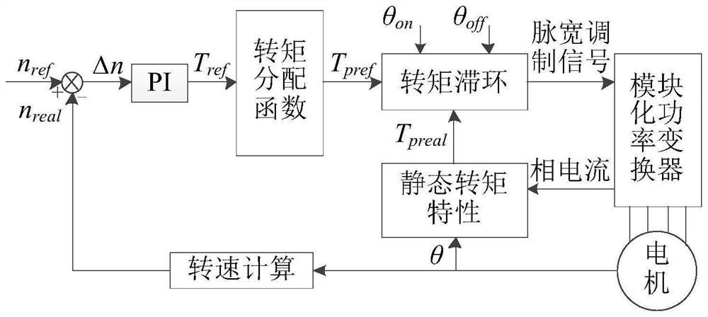
[0015] The torque control method of the switched reluctance motor driven by the modular power converter includes a speed loop and a torque loop, the outer loop is the speed loop, and the inner loop is the torque loop; the input of the speed loop is the set reference speed n ref and the measured actual speed n real , by n ref -n real Obtain the speed error Δn, take the speed error Δn as the input, and obtain the total reference torque T through PI control ref ;The input of the torque loop is T ref , the actual torque T of each phase preal and the opening angle θ on and the turn-off angle θ off


PUM


Abstract

The invention provides a switched reluctance motor torque control method and a modular power converter, the input of a rotating speed ring is a set reference rotating speed and a measured actual rotating speed, a rotating speed error is obtained, the rotating speed error is used as the input, and a total reference torque is obtained through PI control; the input of the torque ring is the total reference torque, the actual torque of each phase, the turn-on angle and the turn-off angle, and distributing the total reference torque to each phase by using a torque distribution function to obtain a phase reference torque; according to the numerical value relation between the phase reference torque and the actual torque of each phase, a pulse width modulation control signal is obtained through torque hysteresis, and the pulse width modulation control signal is applied to a corresponding switch tube in the modular power converter to complete control. On-line self-adjustment is carried out on an overlapping angle in a torque distribution function at each sampling moment, torque hysteresis is based on a pulse width modulation algorithm, pulse width modulation signals with different duty ratios and polarities are generated within a hysteresis limit, and free response is avoided.

Description


Claims


Application Information

Patent Timeline
Owner NORTHWESTERN POLYTECHNICAL UNIV
Why Eureka
Try Eureka