High-selectivity electromagnetic bandgap device and antenna system

Active Publication Date: 2006-01-26
PENN STATE RES FOUND
View PDF10 Cites 29 Cited by
  • Summary
  • Abstract
  • Description
  • Claims
  • Application Information

AI Technical Summary

Benefits of technology

[0008] It is a further object, feature, or advantage of the present invention to enable creation of an antenna system possessing generally narrow bandwidths such that the antenna system will screen out adjacent signals thereby providing radio system selectivity.
[0009] Yet another object, feature, or advantage of the present invention is to add tunability to an EBG to give overall antenna system frequency agility.
[0010] A still further object, feature, or advantage of the present invention is to create an ultra-thin EBG AMC structure with a high-k substrate material that operates effectively well below 1 GHz.
[0011] A still further object, feature, or advantage of the present invention is to use an ultra-thin EBG AMC structure with a high-k substrate material that op

Problems solved by technology

Frequency tunable antennas are known to exist but such antennas do not provide a narrow bandwidth of operation.
Moreover such frequency tunable antennas do not provide for system selectivity.
However, designing such a structure can become quite challenging for low frequency applications, specifically below 1 GHz.
This is mainl

Method used


Image

  • High-selectivity electromagnetic bandgap device and antenna system
  • High-selectivity electromagnetic bandgap device and antenna system
  • High-selectivity electromagnetic bandgap device and antenna system

Examples


Example

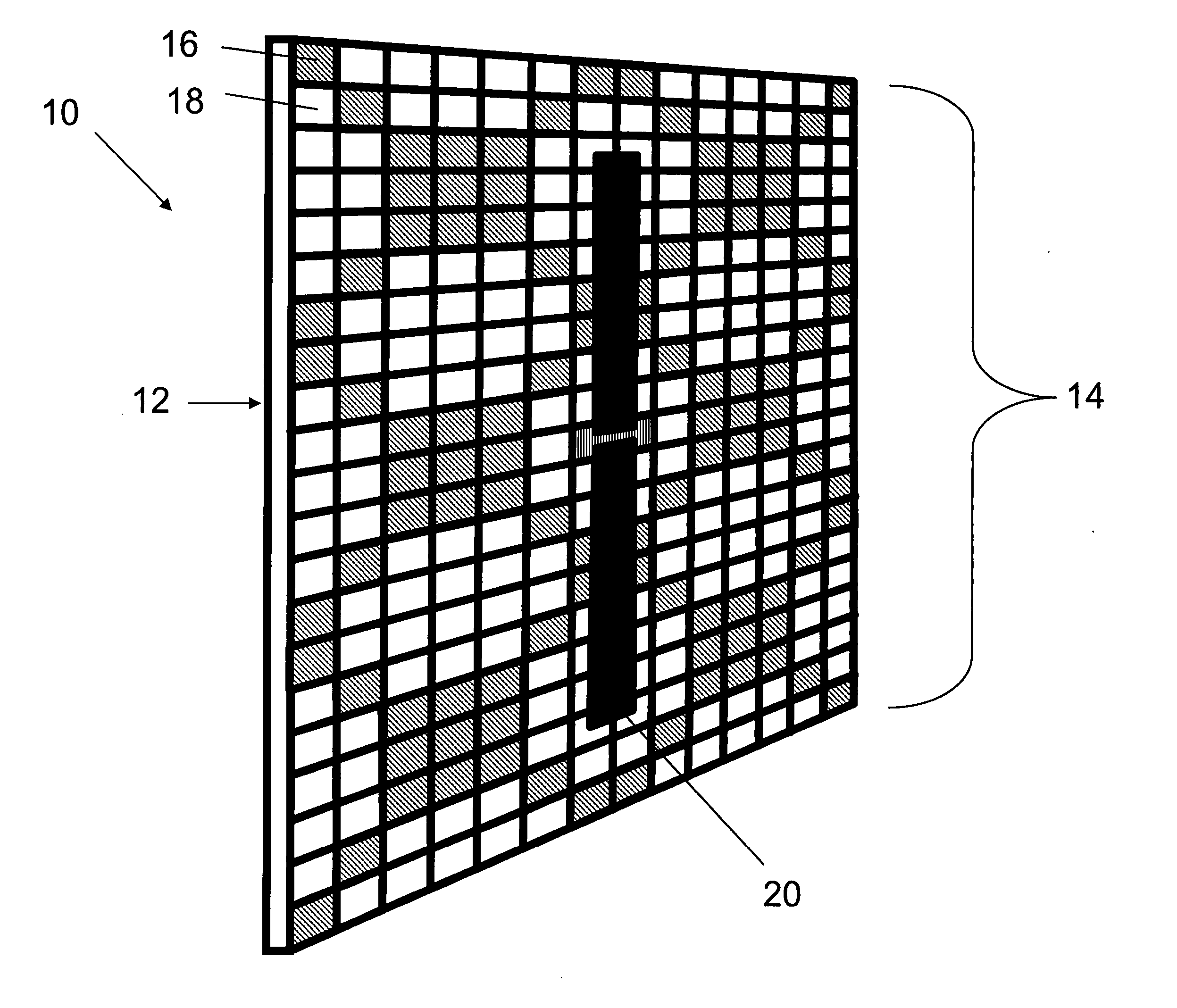
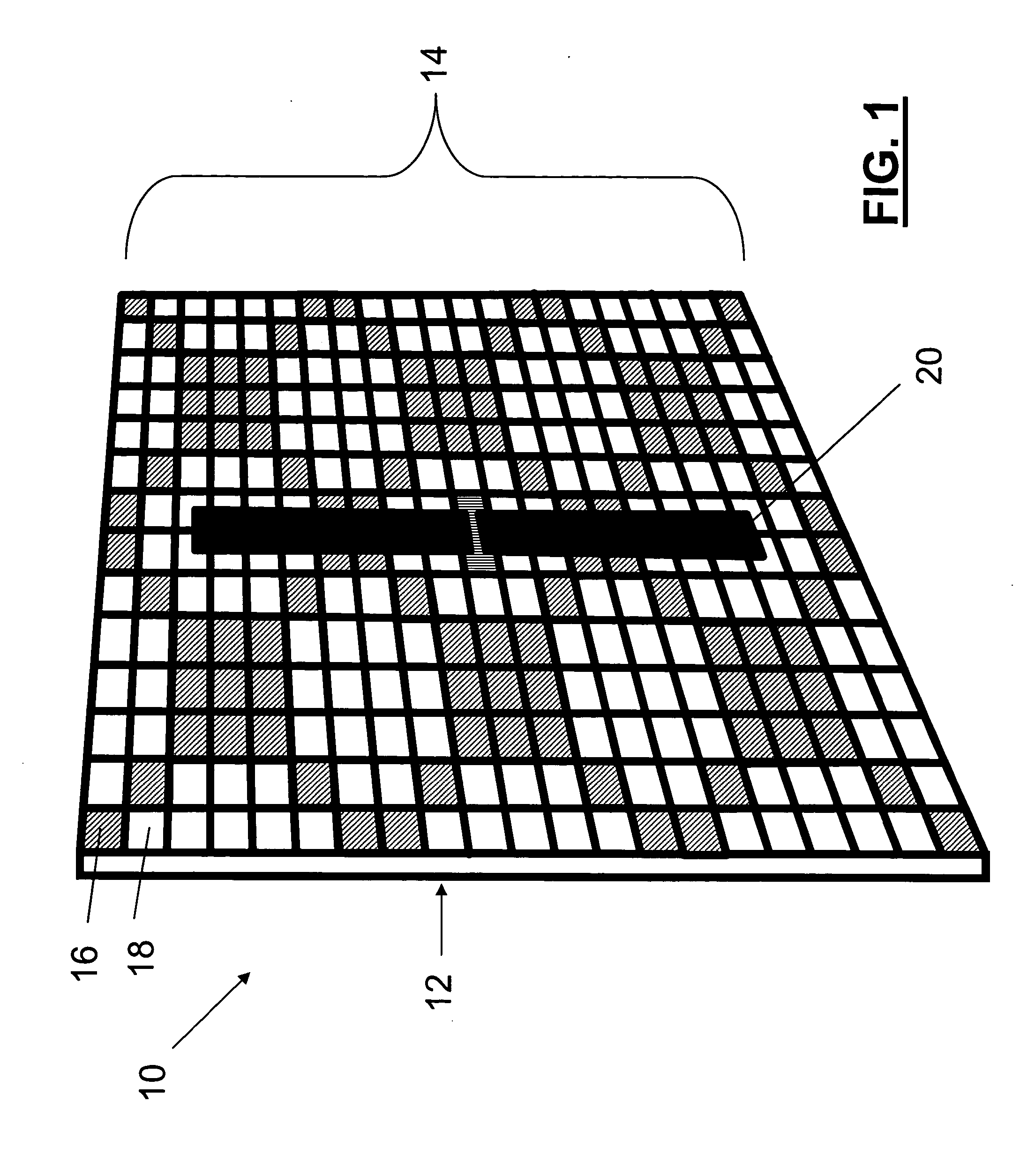
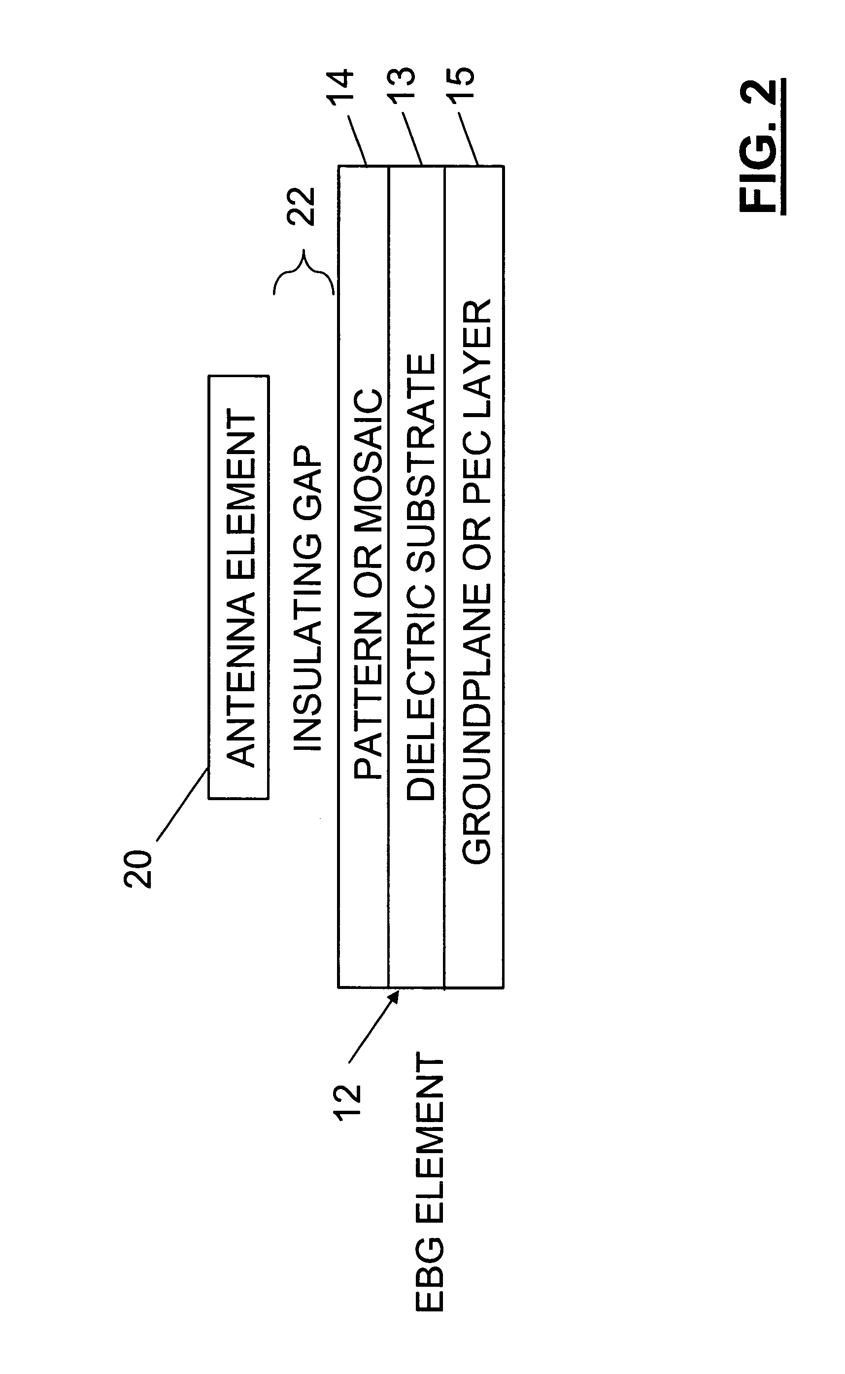
[0027] EBG materials display a reflection phase versus frequency such as that illustrated in FIG. 4. The center frequency of operation is defined as that frequency where the reflection phase is zero. This point on the frequency response curve is very unique. A consequence of zero-phase reflection is that the electric field is not flipped in polarity as is the case for all other electrical conductors (which may be considered perfect electrical conductors (PECs)), but is in fact reflected without a phase shift. This is a unique property that is provided by the operation of these resonant surfaces. In practice, the bandwidth of operation is defined as the frequency range where the reflection phase is between −90 degrees and 90 degrees.

[0028] With this unique property, antennas can be placed proximate (on or near) these surfaces without experiencing the short-circuiting effects associated with PEC ground planes. As the operating frequency with which the antenna is being driven leaves the


PUM


Abstract

An antenna system includes an antenna element and an electromagnetic bandgap element proximate the antenna element wherein the electromagnetic bandgap element is optimized for narrow bandwidth operation thereby providing radiofrequency selectivity to the antenna system. Preferably the electromagnetic bandgap element is tunable such as through use of a bias-alterable dielectric substrate or other tuning mechanism. The design approach also provides a means of creating an ultra-thin low-profile narrowband tunable channel selective antenna system suitable for low frequency applications.

Description


Claims


Application Information

Patent Timeline
Owner PENN STATE RES FOUND
Why Eureka
Try Eureka