Three-Dimensional Measuring Apparatus, Three-Dimensional Measuring Method, And Three-Dimensional Measuring Program

Active Publication Date: 2008-06-05
FUKUOKA INSTITUTE OF TECHNOLOGY
View PDF11 Cites 51 Cited by
  • Summary
  • Abstract
  • Description
  • Claims
  • Application Information

AI Technical Summary

Benefits of technology

[0020](1) The pattern of light formed by the pattern forming means is projected onto a measurement object by the projecting means, an image of the measurement object illuminated with the pattern of light is captured by the imaging means, and a projected pattern of light is detected on this image by the projected pattern light detection means. It is thus possible to obtain many pieces of information on a projected pattern of light by a single projection. Additionally, the direction angle computing means computes the direction angle of each individual pattern of light in the projected pattern of light, and the dividing means divides the projected pattern of light at every cycle. The phase value computing means computes the phase value at each measuring point of an individual pattern of light or a divided projected pattern of light, and the computed phase value at each measuring point is converted into the depth distance of each measuring point. It is thus possible to obtain three-dimensional information not only on one measuring point, at which the intensity distribution of each individual pattern of light in the projected pattern of light takes on a relative maximum, but also on each measuring point of an individual pattern of light. Thus, highly accurate three-dimensional information can be provided.
[0021](6) Since the pattern that is used with the three-dimensional measuring apparatus of the present invention is formed in the shape of stripes. It is thus possible to readily analyze, as a sine wave, the intensity distribution of a projected pattern of light used for analysis.

Problems solved by technology

However, because laser light is likely to have adverse effects on the human body, these methods are difficult to apply to the human body.
However, a reduction in the intensity of laser light, in turn, requires an increase in the time of exposure to it, thereby resulting in the total amount of laser light being increased.

Method used


Image

  • Three-Dimensional Measuring Apparatus, Three-Dimensional Measuring Method, And Three-Dimensional Measuring Program
  • Three-Dimensional Measuring Apparatus, Three-Dimensional Measuring Method, And Three-Dimensional Measuring Program
  • Three-Dimensional Measuring Apparatus, Three-Dimensional Measuring Method, And Three-Dimensional Measuring Program

Examples


Example

EXPLANATION OF REFERENCE NUMERALS

[0037]1: Pattern projector

[0038]2, 2a, 2b, 2c: Camera

[0039]3: Computer

[0040]4: Transmission cable

[0041]10: Storage means

[0042]11: Initial pattern forming means

[0043]12: Optimum pattern forming means

[0044]13: Extracting means

[0045]14: Projected pattern light detection means

[0046]15: Correcting means

[0047]16: Direction angle computing means

[0048]17: Dividing means

[0049]18: Phase value computing means

[0050]19: Distance computing means

[0051]20: Three-dimensional information computing means

[0052]21: Output means

BEST MODE FOR CARRYING OUT THE INVENTION

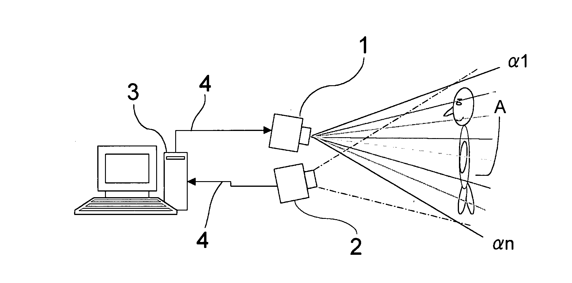
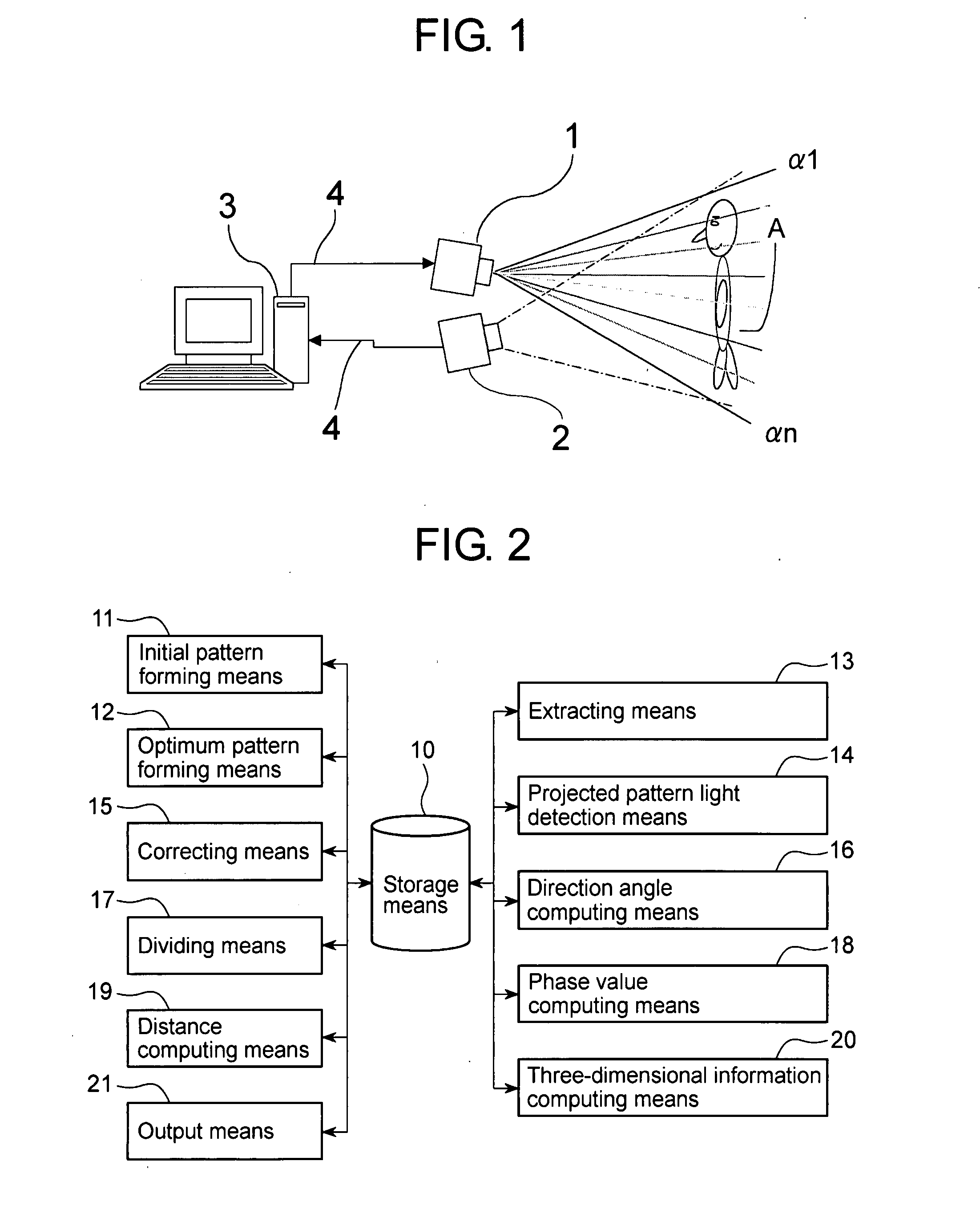
[0053]A description will now be given regarding a three-dimensional measuring apparatus according to an embodiment of the present invention with reference to the drawings. FIG. 1 is a view illustrating the entire configuration of a three-dimensional measuring apparatus according to the present embodiment. FIG. 2 is a block diagram illustrating the detailed configuration of the three-dimensional measuring apparat


PUM


Abstract

A three-dimensional measuring apparatus, method, and program for acquiring many pieces of information on a pattern of light by a single projection and highly accurate three-dimensional information at high speed. The three-dimensional measuring apparatus comprises a pattern projector (1) serving as projecting means for projecting a pattern of light onto a measurement object (A), a camera (2) serving as imaging means for capturing an image of the measurement object (A) illuminated with the pattern of light, and a computer (3) for processing data on the image captured by the camera (2). The computer (3) computes the direction angle of each individual pattern of light which forms the projected pattern of light from the intensity value of the projected pattern of light detected from the captured image, divides the intensity distribution, and computes the depth distance from the phase value at each measuring point of the divided pattern. Thus, highly accurate three-dimensional information is acquired.

Description


Claims


Application Information

Patent Timeline
Owner FUKUOKA INSTITUTE OF TECHNOLOGY
Why Eureka
Try Eureka