Elliptical Polarizer and Vertical Alignment Type Liquid Crystal Display Device Comprising the Same

Inactive Publication Date: 2010-02-04
NIPPON OIL CORP
View PDF22 Cites 40 Cited by
  • Summary
  • Abstract
  • Description
  • Claims
  • Application Information

AI Technical Summary

Benefits of technology

[0071]The vertical alignment type liquid crystal display device of the present invention is bright in images and capable of displaying images of high contrast in all the directions.

Problems solved by technology

Thereupon, it is difficult to align uniformly the liquid crystal molecules.
The use of a conventional alignment treatment, i.e., rubbing treatment leads to a significant reduction in display quality.
However, a vertical alignment type liquid crystal display device with circular polarizers has a problem that the viewing angle characteristics are narrower than a vertical alignment type liquid crystal display device with linear polarizers.
However, the optical anisotropic element with a negative uniaxial anisotropy can compensate the positive uniaxial optical anisotropy in the liquid crystal cell thickness direction but can not compensate the viewing angle characteristics of a ¼ wavelength plate, resulting in a failure to obtain sufficient viewing angle characteristics.
Therefore, there is a limit in stretching in the thickness direction and thus the retardation in the thickness direction can not be controlled within a wide rage.
The thickness of the retardation film produced by the method is from 50 to 100 μm and is insufficient for low profiling required in liquid crystal display devices or the like.
Therefore, they can significantly improve the viewing angle but are not practical in view of production cost and thickness.(1) Patent Document 1: Japanese Patent Application Laid-Open Publication No. 2002-40428(2) Patent Document 2: Japanese Patent Application Laid-Open Publication No. 2003-207782(3) Patent Document 3: Japanese Patent Application Laid-Open Publication No. 2002-55342(4) Patent Document 4: Japanese Patent Application Laid-Open Publication No. 2006-85203

Method used


Image

  • Elliptical Polarizer and Vertical Alignment Type Liquid Crystal Display Device Comprising the Same
  • Elliptical Polarizer and Vertical Alignment Type Liquid Crystal Display Device Comprising the Same
  • Elliptical Polarizer and Vertical Alignment Type Liquid Crystal Display Device Comprising the Same

Examples


Example

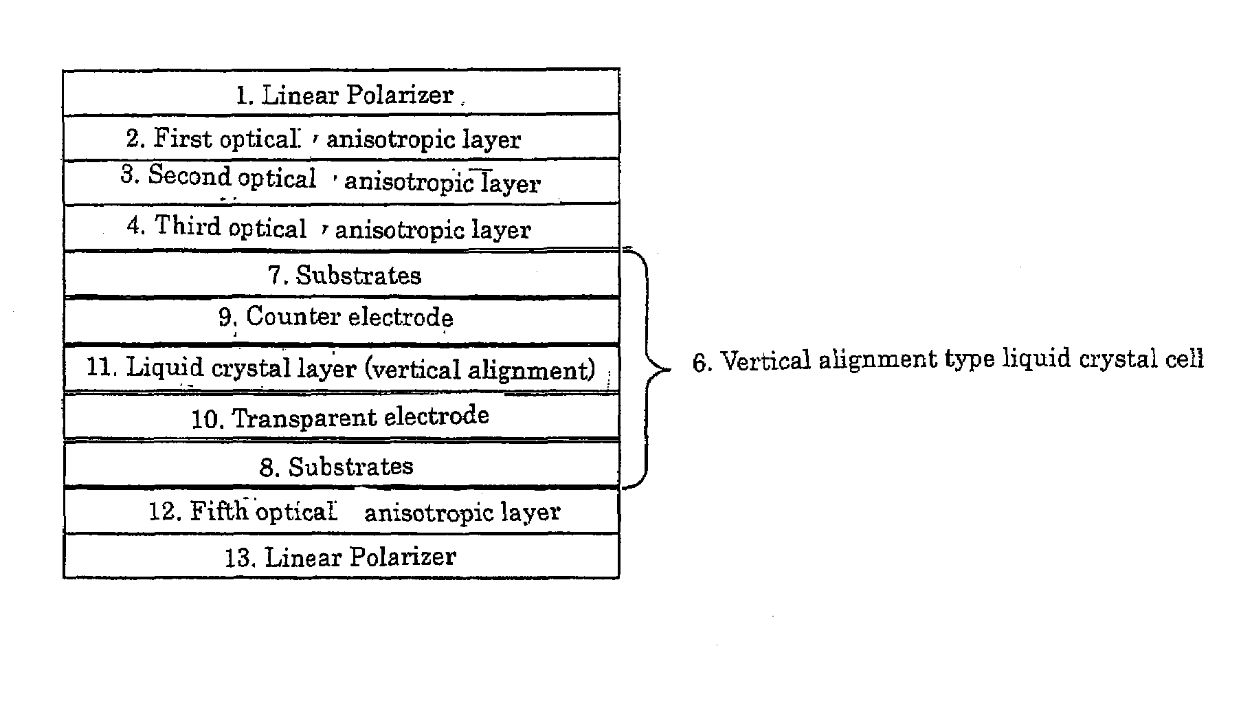
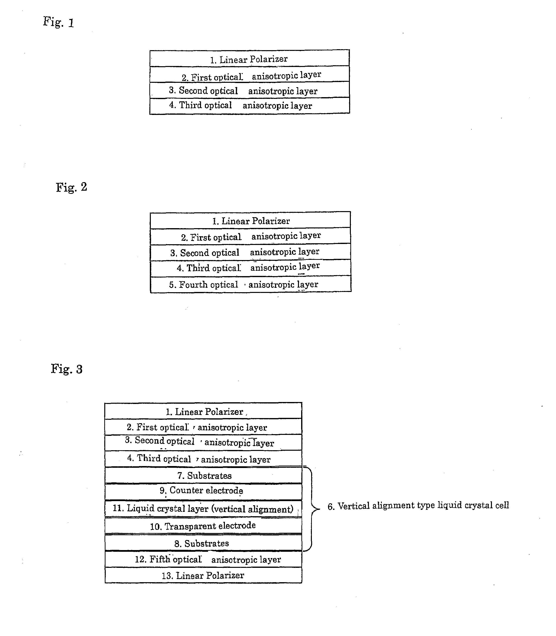
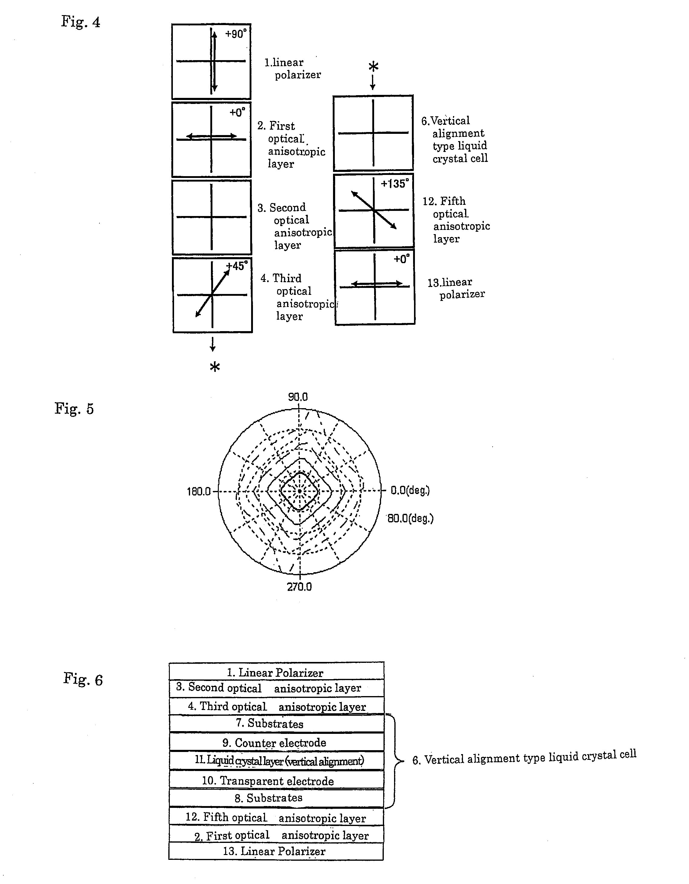
[0294]1, 13: linear polarizer, 2, 15: first optical anisotropic layer, 3, 16: second optical anisotropic layer, 4: third optical anisotropic layer, 5: fourth optical anisotropic layer, 12: fifth optical anisotropic layer, 7,8: substrate, 10: transparent electrode, 9: counter electrode, 15: reflective electrode, 11: liquid crystal layer (vertical alignment), 6: vertical alignment type liquid crystal cell, 14: transflective vertical alignment type liquid crystal cell

APPLICABILITY IN THE INDUSTRY

[0295]The vertical alignment type liquid crystal display device of the present invention is bright in images and capable of displaying images of high contrast in all the directions and thus has a large industrial value.


PUM


Abstract

An elliptical polarizer with excellent viewing angle characteristics is provided which comprises at least a first polarizer, a first optical anisotropic layer, a second optical anisotropic layer, and a third optical anisotropic layer, laminated in this order, wherein the first optical anisotropic layer satisfies [1] 50≦Re1≦500, the second optical anisotropic layer satisfies [2] 0≦Re2≦20 and [3]−500≦Rth2≦−30, and the third optical anisotropic layer satisfies [4] 100≦Re 3≦180 wherein Re and Rth indicate the retardation values in the plane and thickness direction, respectively, of each of the optical anisotropic layers.

Description


Claims


Application Information

Patent Timeline
Owner NIPPON OIL CORP
Why Eureka
Try Eureka