Pulse analyzer

a pulse analysis and pulse technology, applied in the field of pulse analysis, can solve the problem of high cost of ultra-fast sampling circuits

Active Publication Date: 2010-11-25
MITSUBISHI ELECTRIC R&D CENTRE EUROPE BV
View PDF11 Cites 4 Cited by
  • Summary
  • Abstract
  • Description
  • Claims
  • Application Information

AI Technical Summary

Benefits of technology

The present inventor's new way of processing pulses allows for instantaneovered value data that can be produced with no costly equipment at all times. This results in more efficient production of signals than traditional methods like time slice or analogue circuitry techniques.

Problems solved by technology

This patented technical problem addressed in this patents relates to developing cost-effective methods for acquiring high quality signals from long pulses with unknown shapes without sacrificing their temporal resolution or accuracy.

Method used


Image

  • Pulse analyzer
  • Pulse analyzer
  • Pulse analyzer

Examples


Embodiment Construction

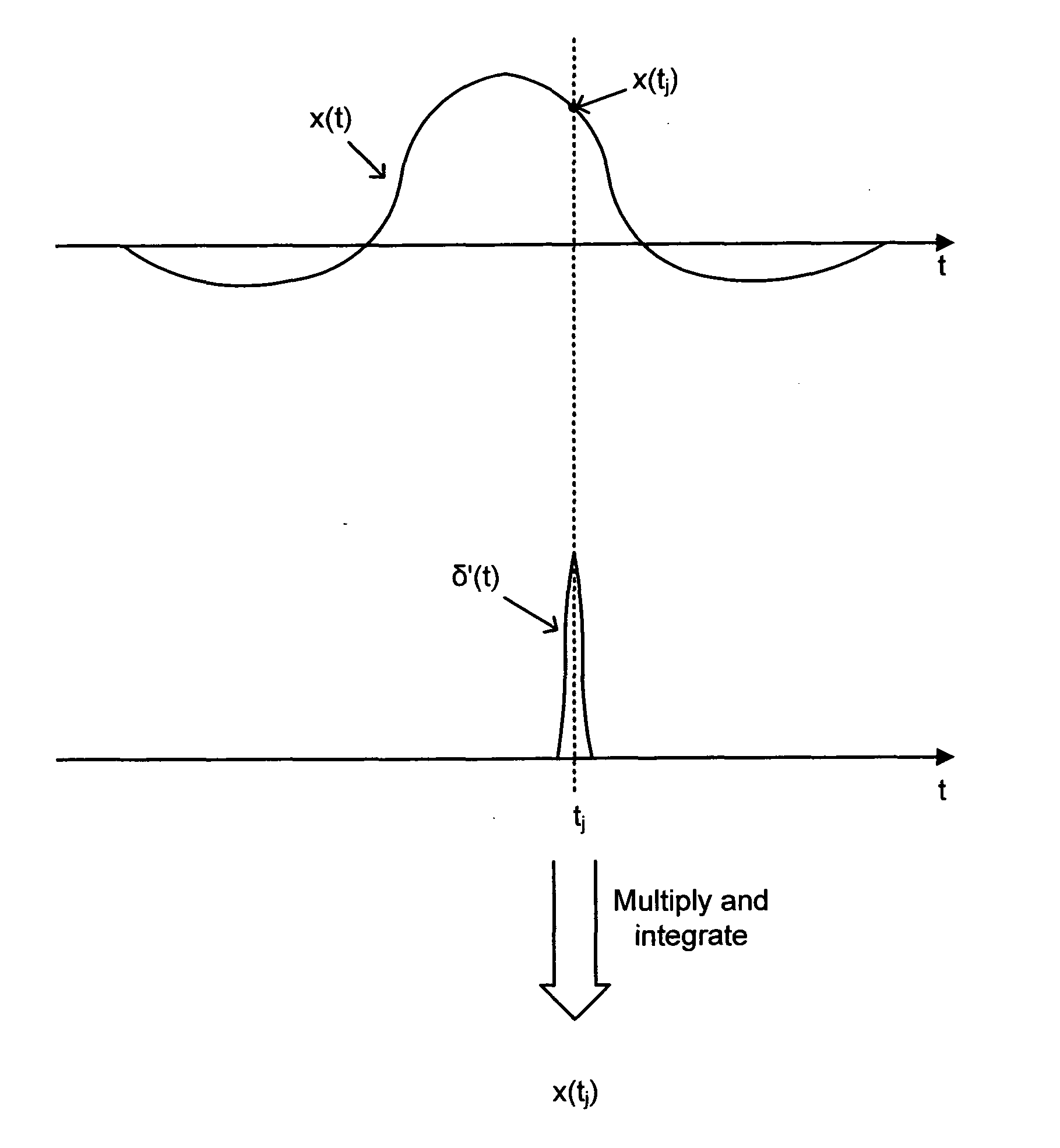
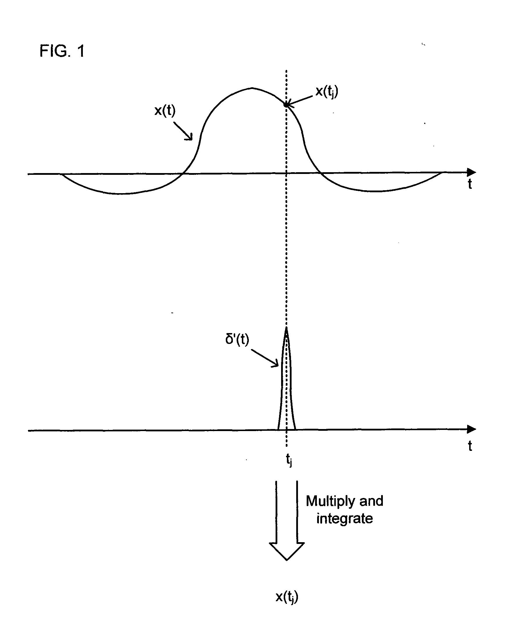
[0016]Suppose that a wideband pulse x(t) of finite duration and unknown shape is to be sampled at a plurality of J time instants t1, t2, . . . , tj, . . . , tJ. It is assumed that the pulse duration is limited by some maximum value T, and that the pulse time-of-arrival is approximately known. The acquired samples of the pulse x(t) are then used to determine some pulse descriptors such as shape and its moments, including location and time spread. The pulse under examination may be regarded as being observed at the output of a suitable sensor that has captured a portion of electromagnetic radiation scattered by a remote object of interest.

[0017]From the ‘sifting’ property of the Dirac delta function, or Dirac impulse, δ(t) it follows that a sample at time tj of a pulse x(t), i.e. the value x(tj), can be determined from the integral

x(tj)=∫0Tx(t)δ(t-tj)t

[0018]FIG. 1 depicts an example of a pulse x(t) being sampled at time tj with the use of a function δ′(t) approximating the Dirac impulse


PUM


Abstract

There is described a pulse analyser (1) for sampling a pulse or a repetitive stream of pulses. The pulse analyser multiplies a pulse by a set of basis functions (c1, c2) to generate a plurality of multiplied pulse functions, and a synthesiser (9a, 9b, 13) combines the multiplied pulse functions to generate a pulse sample. In particular, the synthesiser performs at least one integrating operation over an integration interval substantially corresponding to the duration of the pulse and at least one adding operation. The basis functions are such that the output of the synthesiser corresponds to a pulse sample for a sample time interval shorter than the integration interval.

Description


Claims


Application Information

Patent Timeline
Owner MITSUBISHI ELECTRIC R&D CENTRE EUROPE BV
Why Eureka
Try Eureka