Elevation angle estimation in horizontal antenna array with doppler and velocity measurements

a technology of horizontal antenna array and velocity measurement, which is applied in the direction of instruments, measurement devices, antennas, etc., can solve the problems of reducing the ability of radar antennas to determine elevation information, adding weight and cost to vehicles,

Active Publication Date: 2020-12-17
GM GLOBAL TECH OPERATIONS LLC
View PDF0 Cites 2 Cited by
  • Summary
  • Abstract
  • Description
  • Claims
  • Application Information

AI Technical Summary

Benefits of technology

This patent describes a system that uses radar technology to detect objects within its own environment. It can also calculate their velocities and use this data to guide vehicles through obstacles like buildings.

Problems solved by technology

The technical problem addressed by this patent is how to accurately measure the height or position (height) of an object using a radar system with multiple antennas arranged horizontally instead of just one.

Method used


Image

  • Elevation angle estimation in horizontal antenna array with doppler and velocity measurements
  • Elevation angle estimation in horizontal antenna array with doppler and velocity measurements
  • Elevation angle estimation in horizontal antenna array with doppler and velocity measurements

Examples


Embodiment Construction

[0020]The following description is merely exemplary in nature and is not intended to limit the present disclosure, its application or uses. It should be understood that throughout the drawings, corresponding reference numerals indicate like or corresponding parts and features.

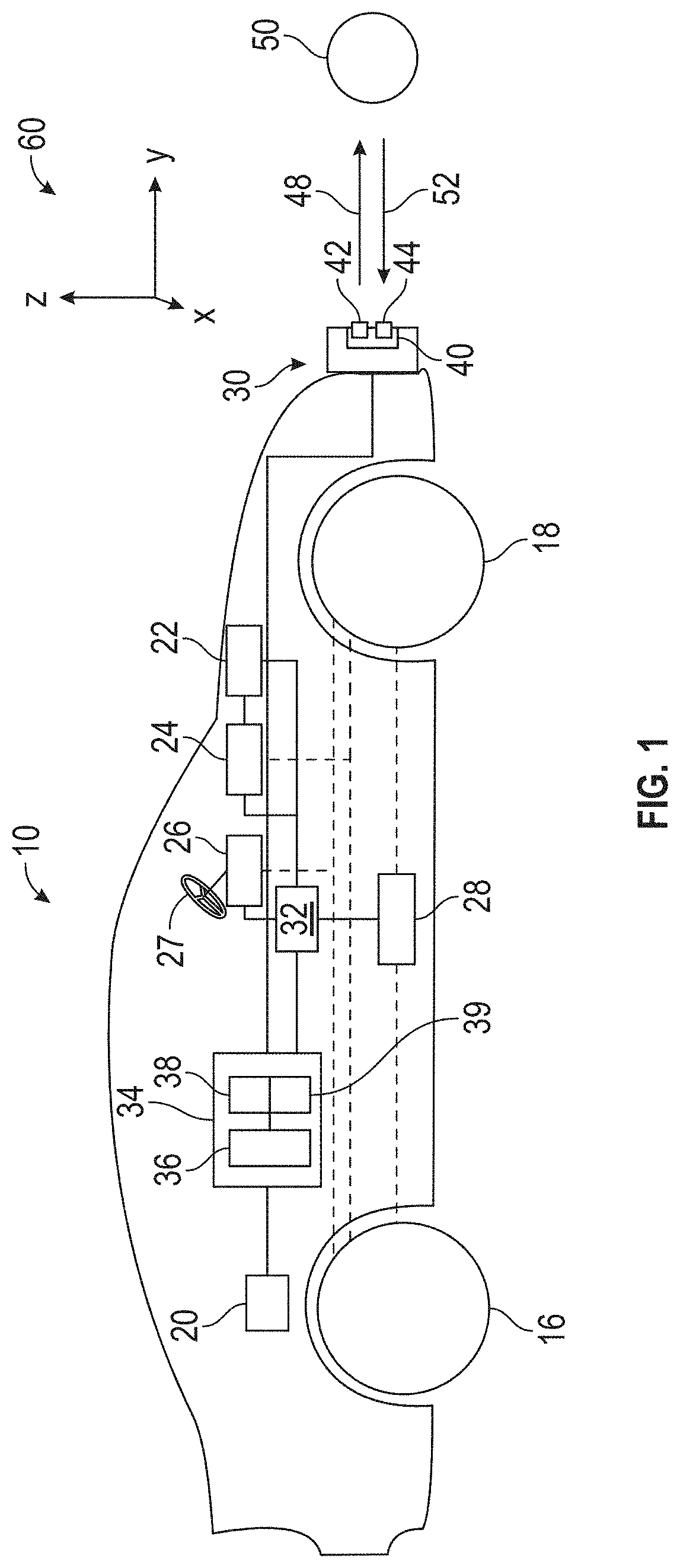
[0021]In accordance with an exemplary embodiment, FIG. 1 shows an autonomous vehicle 10. In an exemplary embodiment, the autonomous vehicle 10 is a so-called Level Four or Level Five automation system. A Level Four system indicates “high automation”, referring to the driving mode-specific performance by an automated driving system of all aspects of the dynamic driving task, even if a human driver does not respond appropriately to a request to intervene. A Level Five system indicates “full automation”, referring to the full-time performance by an automated driving system of all aspects of the dynamic driving task under all roadway and environmental conditions that can be managed by a human driver.

[0022]The autonomo


PUM


Abstract

A vehicle, radar system of the vehicle and method of determining an elevation of an object. The radar system includes a transmitter that transmits a reference signal and a receiver that to receive at least one echo signal related to reflection of the reference signal from an object. The receiver includes an antenna array having a plurality of horizontally-spaced antenna elements. A processor determines a first uncertainty curve associated with an azimuth measurement related to the at least one echo signal, determines a second uncertainty curve associated with a Doppler measurement and a velocity measurement related to the at least one echo signal, and locates an intersection of the first uncertainty curve and the second uncertainty curve to determine the elevation of the object.

Description


Claims


Application Information

Patent Timeline
Owner GM GLOBAL TECH OPERATIONS LLC
Why Eureka
Try Eureka