Method for controlling a group of glow plugs in a diesel engine

A diesel engine and glow plug technology, which is applied to the incandescent ignition of the engine, engine ignition, engine control, etc., can solve the problems of non-use and undesired temperature of the glow plug, and achieve the effect of prolonging the service life.

Inactive Publication Date: 2008-09-17
BERU AG DE
View PDF0 Cites 15 Cited by
  • Summary
  • Abstract
  • Description
  • Claims
  • Application Information

AI Technical Summary

Problems solved by technology

However, this has the disadvantage that glow plugs, which are normally supposed to operate at higher temperatures, will operate at lower temperatures as a precautionary measure, so that part of their effic

Method used


Image

  • Method for controlling a group of glow plugs in a diesel engine

Examples


Embodiment Construction

[0038] The following applies all said three solutions to the object of the invention:

[0039] The term relative pulse width is used here to describe the pulse width in relation to the length of the modulation period. Preferably, the period is constant and only the pulse width is varied. However, it is also possible to keep the pulse width constant and vary the period.

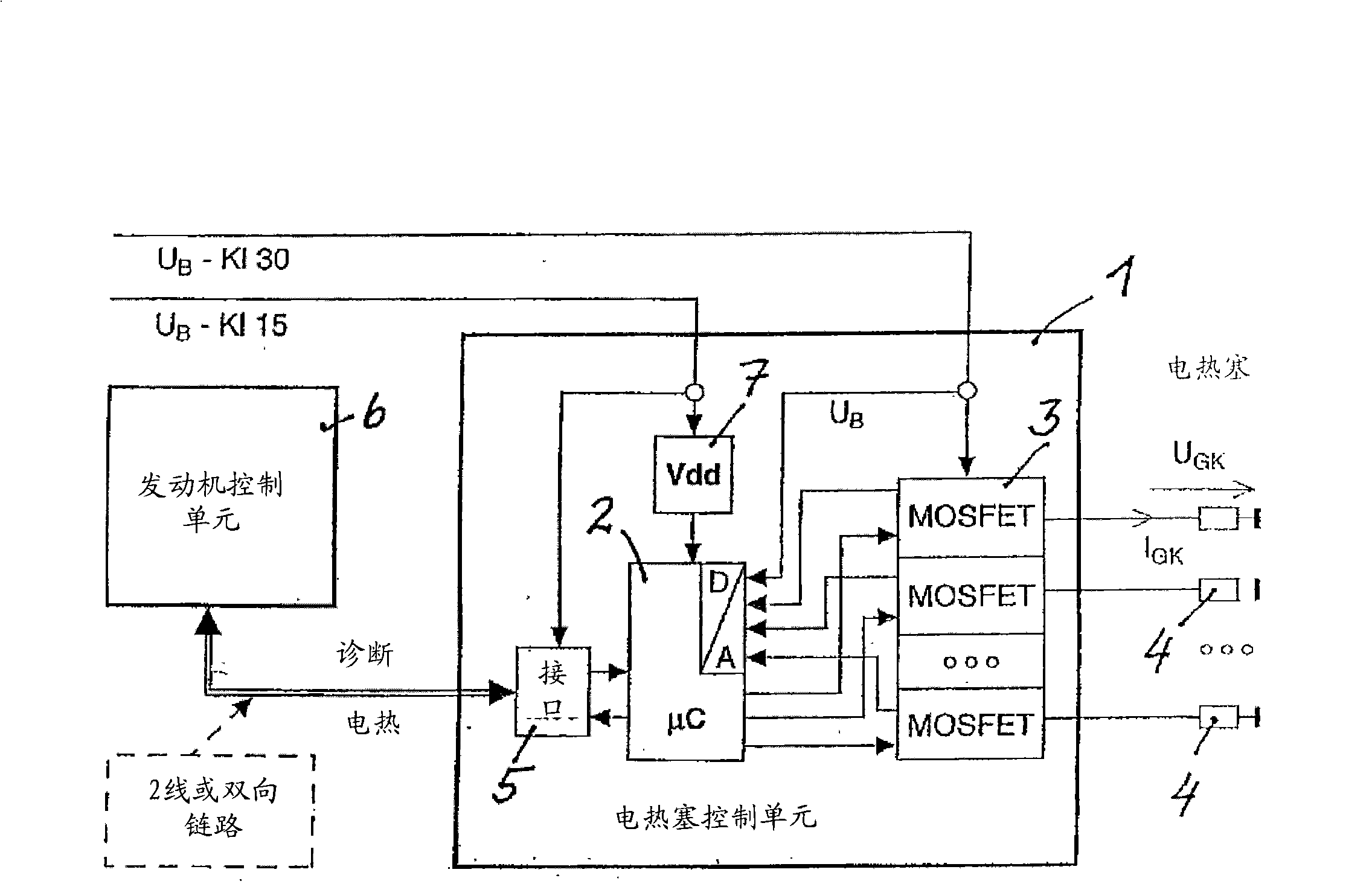
[0040] Another advantage of the invention can be seen in fact that, in addition to the resistance of the glow plugs, other parameters influencing the temperature of the individual glow plugs are likewise used as input parameters by pulse modulation for the work, thereby being used for the work of each glow plug. One such parameter, advantageously used as input parameter for said pulse width modulation control, is the voltage of the DC power supply to said glow plugs, in particular the voltage of the battery of a vehicle equipped with a diesel engine. The voltage will vary with the current load, the temperature


PUM


Abstract

The invention relates to a method for controlling a group of glow plugs for a diesel engine, which are connected to a direct current supply by individual supply lines and operat by a pulse width modulation method in any case at the same temperature in the time average. The inventive method consists in calculating the electric resistance of the glow plugs, in subtracting the resistance of the plug glowing element supply line therefrom during the engine operation for calculating a relative pulse width with which the glow plugs are controlled or in determining for each glow plug the resistance of the glowing element thereof during the engine operation, thereby making it possible to calculate the individual relative pulse width for individually controlling each glow plug or also to determine the electric energy supplied by period to the glow plugs by means of the pulse width modulation.

Description


Claims


Application Information

Patent Timeline
Owner BERU AG DE
Why Eureka
Try Eureka