Shielded flat cable

A technology for flat cables and flat conductors, applied in the direction of flat/ribbon cables, insulated cables, cables, etc., can solve the problems of not clarifying the impedance of the cable end, not clearly recording the structure of the end, and unable to clarify the relationship of characteristic impedance, etc., to achieve Good signal transmission, the effect of reducing the change of characteristic impedance

Active Publication Date: 2010-09-22
SUMITOMO ELECTRIC IND LTD
View PDF2 Cites 8 Cited by
  • Summary
  • Abstract
  • Description
  • Claims
  • Application Information

AI Technical Summary

Problems solved by technology

However, the structure of the end portion is not clearly described, and the impedance near the end portion of the cable is not clarified.
Also, although it is disclosed that a metal coupling part f

Method used


Image

  • Shielded flat cable
  • Shielded flat cable
  • Shielded flat cable

Examples


Example Embodiment

[0019] Hereinafter, embodiments of the present invention will be described with reference to the drawings. The drawings are for illustrative purposes and are not used to limit the scope of the invention. In the drawings, in order to avoid repeated description, the same reference numerals denote the same parts. In addition, the size ratios in the drawings may not be accurate.

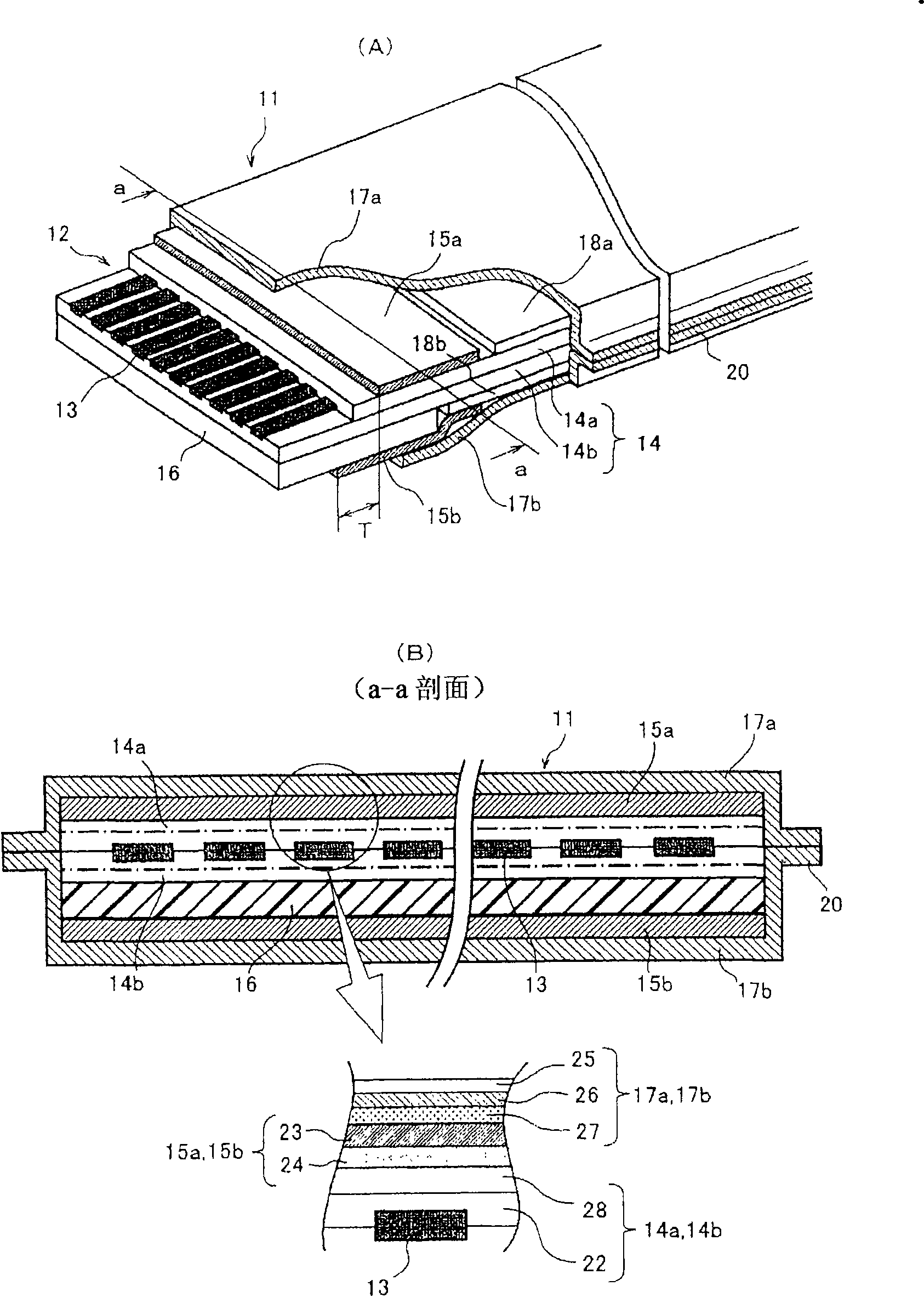
[0020] figure 1 (A) is a perspective view showing the end portion of the shielded flat cable 11 according to the embodiment of the present invention. In the shielded flat cable 11, a plurality of flat conductors 13 are insulated by sandwiching the upper film 14a (the first insulating resin film) and the lower film 14b (the second insulating resin film) as the insulating resin film 14 from above and below. Cladding. In addition, the upper film 14a is removed at at least one end thereof, and the portion of the flat conductor 13 serving as the connection terminal is exposed, and the cable end portion 12 is fo


PUM


Abstract

The invention provides a shielded flat cable. The whole length of the shielded flat cable is shielded, and the impedance change of the tail end of the cable is smaller; one side of an insulating resin film (14) is removed to lead a flat conductor (13) to be exposed, and a reinforcing band (16) is pasted on the external surface of the other side of the insulating resin film (14), thus forming a cable tail end (12); shielded films (17a, 17b) are cladded on the external surface of the insulating resin film (14), thus the impedance is set to be a specified value; in addition, the insulating resin film (14a) at the side, from which the flat conductor is exposed, of the cable tail end (12) reserves a specified distance so as to be pasted with a first earth tape (15a), the side at which the reinforcing band (16) is arranged reserves a distance relative to the front end so as to be pasted with a second earth tape (15b); and the first earth tape and the second earth tape are electrically connected with the shielded films (17a, 17b) through overlapping parts.

Description


Claims


Application Information

Patent Timeline
Owner SUMITOMO ELECTRIC IND LTD
Why Eureka
Try Eureka