Load support structure

A technology for supporting structure and load, applied in the direction of benches, chairs, stools, etc., can solve the problem of unable to form a healthy posture, a hunched posture, etc., and achieve the effect of easy return to an upright sitting position

Active Publication Date: 2010-10-20
HERMAN MILLER INC
View PDF9 Cites 11 Cited by
  • Summary
  • Abstract
  • Description
  • Claims
  • Application Information

AI Technical Summary

Benefits of technology

This technology allows one's head restraint system (HSS) to move upward or downwards depending on how much pressure they are putting their weight onto them while leaning backwards at different angles with respect to gravity. By doing that, these systems make sure users get comfortable sleeping without getting too hard pressed into an incorrect posture.

Problems solved by technology

The technical problem addressed in this patented text relating to adjustable chairs for users who are heavier than usual (users) while also ensuring they can maintain their natural pose during use without causing harmful pressure from external factors such as gravity).

Method used


Image

  • Load support structure
  • Load support structure
  • Load support structure

Examples


Embodiment Construction

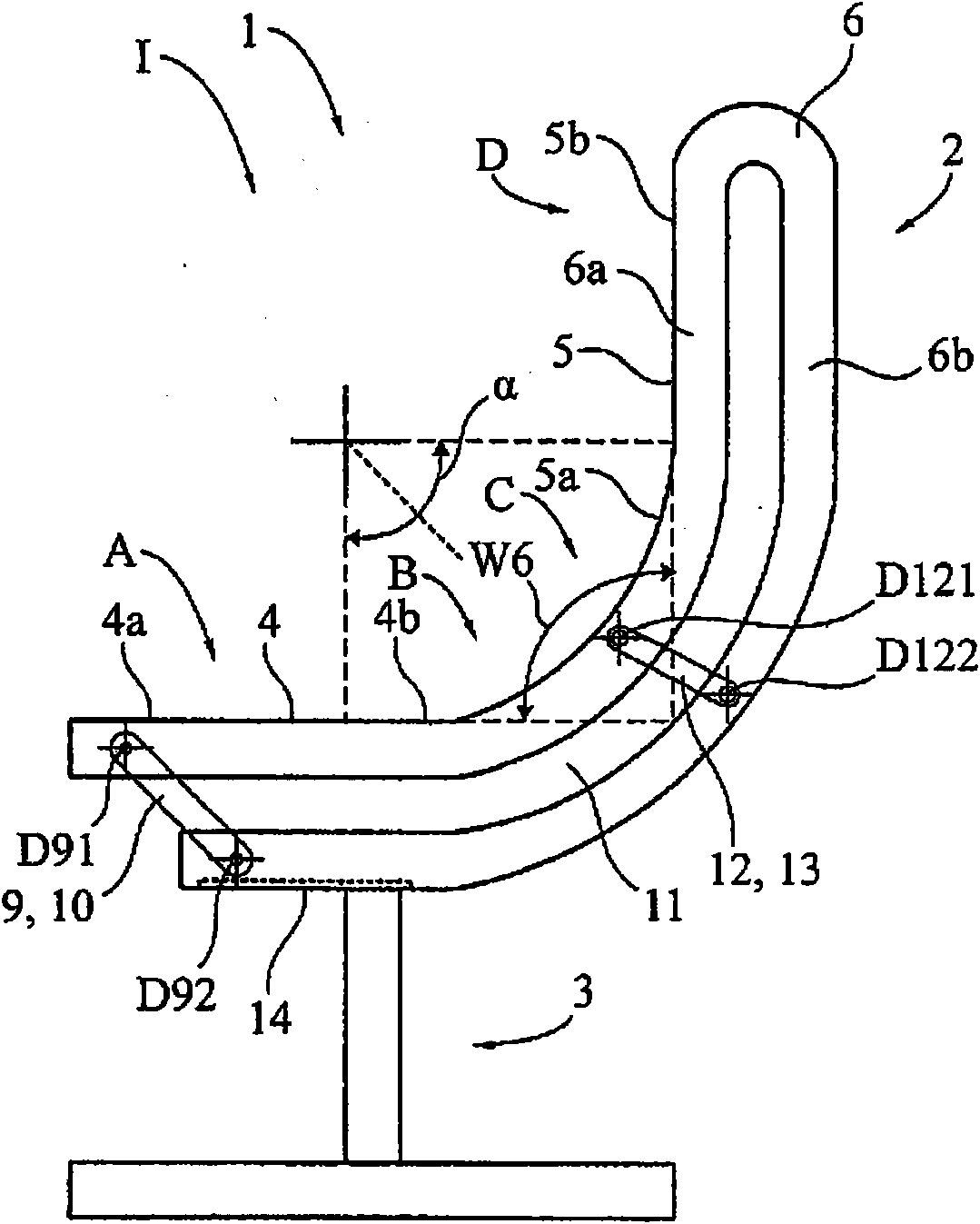
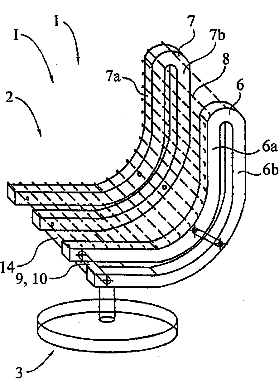
[0100] Figure 1a The socket 1 is illustrated in side view. The seat 1 comprises a seat element 2 and a lower frame 3 . The seat element 2 has a seat part 4 which is divided into a front seat part 4a and a rear seat part 4b. Furthermore, the seat element 2 also has a backrest part 5 which is divided into a lower backrest part 5a and an upper backrest part 5b. The seat element 2 comprises two support arms 6, 7 (or beam or carrier members), each support arm 6, 7 consisting of an upper support portion 6a or 7a (or first beam member) and a lower support portion 6b or 7b ( or second beam member) formed (see also Figure 1b ). only at Figure 1b The fabric 8 visible in is stretched between the two support arms 6, 7 and their upper supports 6a, 7a. Other body support members, such as shells or membranes (alone or in combination with fabric), may also bridge between the two support arms.

[0101] Figure 1b A simplified perspective view of the seat 1 shown in Figure 1 is shown. F


PUM


Abstract

A load support member includes spaced apart beam members, a linking member and a stop member. In another aspect, the beam includes a support surface defining first and second landing regions, which are in contact with and support a membrane. In another aspect, a brace member is secured between laterally spaced beams, with the brace member having a greater height than width at the end thereof and a greater width than height at the middle thereof. In another aspect, a pair of armrests are joined to a cross member and a pair of spaced apart beams in a releasable engagement. In yet another aspect, a pair of beam members are fixedly joined with a cross member, which is pivotally connected to a link pivotally connected to the beams. A method of assembling a load support structure is also provided.

Description


Claims


Application Information

Patent Timeline
Owner HERMAN MILLER INC
Why Eureka
Try Eureka