Rail vehicle

A technology for motor vehicles and carriages, applied in the field of rail vehicles

Inactive Publication Date: 2012-01-11
SIEMENS AG
View PDF5 Cites 6 Cited by
  • Summary
  • Abstract
  • Description
  • Claims
  • Application Information

AI Technical Summary

Benefits of technology

This patented technology allows for an improved way of applying electricity into trains without requiring expensive equipment such as transformers. By providing direct connections from one part of the railway car's electrical network to another, it becomes possible to use less costly materials while still delivering effective cooling capabilities on certain parts of the cars. Additionally, there are also technical benefits like enabling fast charging of batteries during emergency situations, allowing passengers more time out before being stricken through fires caused by excessive heat generated inside them. Overall, these improvements make better performance and efficiency within the entire transportation fleet.

Problems solved by technology

This patented describes different technical problem addressed during research into how to improve safety measures on railway systems such as rails due to excessive wear caused from use over time without requiring maintenance work.

Method used


Image

  • Rail vehicle
  • Rail vehicle

Examples


Embodiment Construction

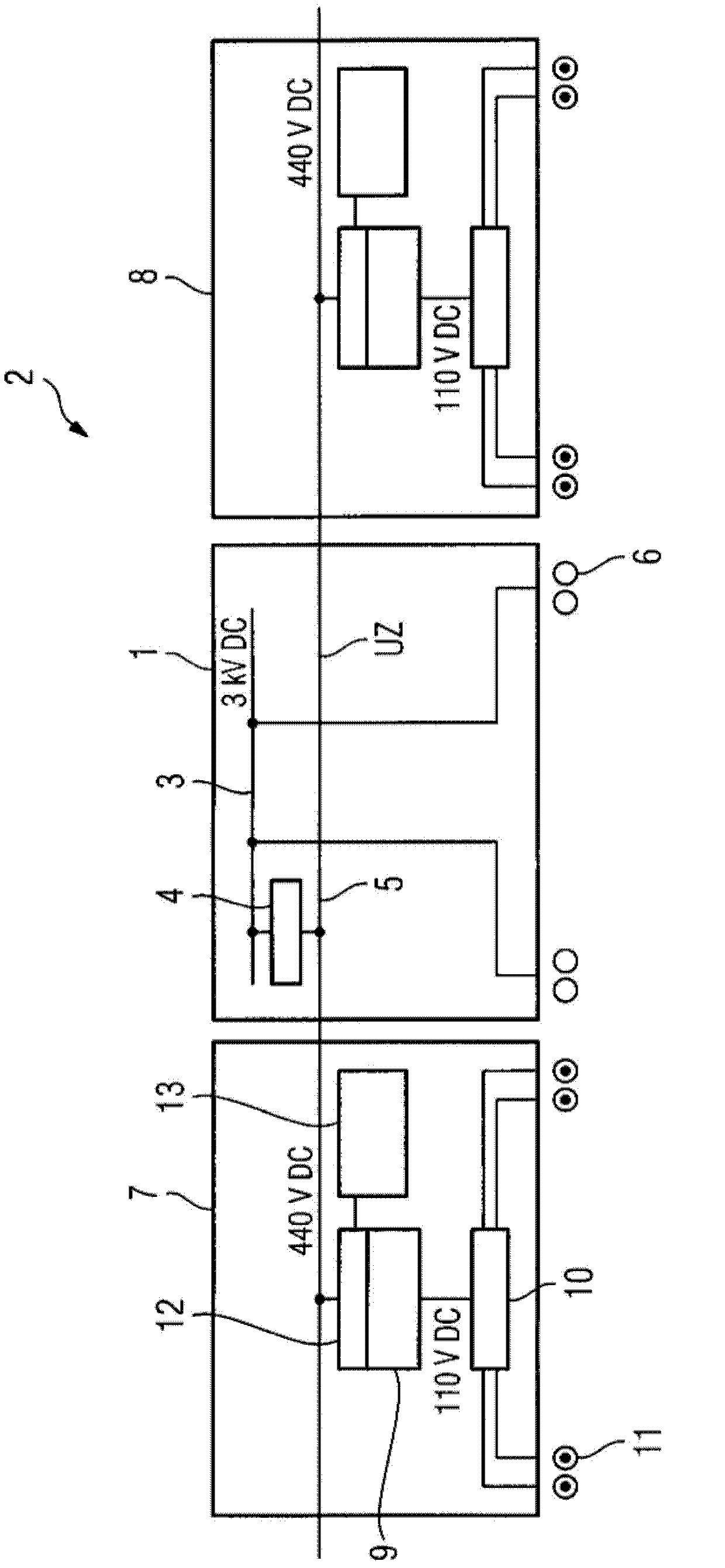
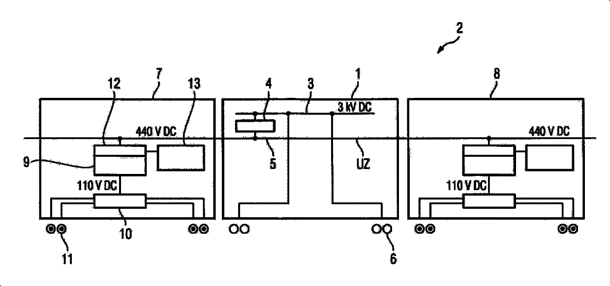
[0015] figure 1 The 1 marked in is the electric motor compartment of the rail vehicle 2. For the sake of clarity, only its traction intermediate circuit 3 and its converter 4 are shown for the motor car 1 . The voltage of the traction intermediate circuit, typically 3 kV DC, is converted by means of the converter 4 into a DC voltage Uz on the train bus 5 , which runs through all the cars of the rail vehicle 2 and is at a voltage level of 440 V DC. The motor car 1 is equipped with an electric motor, not shown, which is fed directly from the intermediate traction circuit. The small circles on the chassis of the motor car 1 shall represent the wheels or axles 6 driven by traction motors not shown.

[0016] In the illustrated rail vehicle 2 there is a first non-driven carriage 7 and a further non-driven carriage 8 on both sides of the electric motor carriage 1 . The two carriages 7 or 8 are here embodied identically in the relevant relation, so that the following description can r


PUM


Abstract

The invention relates to a rail vehicle which comprises at least one motor compartment (1) with power supplied from a traction intermediate circuit (3) and a traction motor, and at least one non-driven compartment (7,8). The non-driven compartment can be braked by a brake controller (10) equipped on the front through an eddy current brake excited through the brake current of the traction motor. The vehicle has an eddy current brake whose brake plate is attached to a train line (5) through an arrangement (9) for providing direct voltage with a significantly lower voltage level of the traction intermediate circuit (3). Therefore, the rail vehicle is cheap and low in energy consumption. The train line (5) is connected with the traction intermediate circuit (3) through an inverter (4). The arrangement (9) for providing DC voltage and the brake controller (10) are equipped in the non-driven compartment.

Description


Claims


Application Information

Patent Timeline
Owner SIEMENS AG
Why Eureka
Try Eureka