Method and device for acquiring vehicle speed signal for automobile combination instrument

A combined instrument and signal technology, which is applied to vehicle components, transportation and packaging, circuits or fluid pipelines, etc., can solve the problems of vehicle safety hazards, combined instruments cannot receive vehicle speed signals, etc., and achieve reliable working results

Inactive Publication Date: 2012-04-18
CHERY AUTOMOBILE CO LTD
View PDF4 Cites 7 Cited by
  • Summary
  • Abstract
  • Description
  • Claims
  • Application Information

AI Technical Summary

Benefits of technology

This patented technology helps improve safety during car navigation systems by accurately detecting if there are any problems with the road wheels or other objects on the route being navigated through it. It uses an integrated circuit called CTM (Composite Terminal Module) chip located between two sensors: one at each side of the steering system's axle shaft. By analyzing this data collected over time, the device can determine whether certain parts have issues such as slippage or damage caused due to poor driving conditions. If they don’t work properly, the devices will gather signals indicating their problematic situation along its way back into the main computer network controller unit.

Problems solved by technology

The technical problem addressed in this patented technology relates to ensuring that combined instruments are always working properly even if one component fails during operation due to either failure mode (BSC) or other factors such as power supply issues).

Method used


Image

  • Method and device for acquiring vehicle speed signal for automobile combination instrument
  • Method and device for acquiring vehicle speed signal for automobile combination instrument

Examples


Embodiment Construction

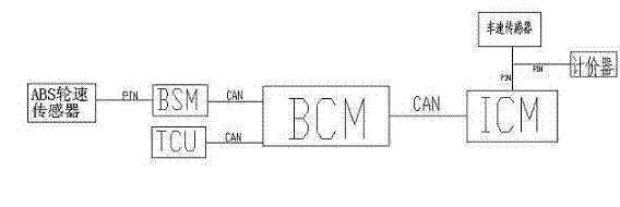
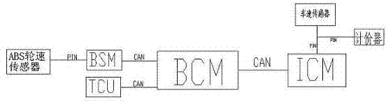
[0017] As shown in the figure, the signal output terminal of the ABS wheel speed sensor is connected to the brake module BSM, the brake module BSM and the transmission control module TCU are respectively connected to the body control module BCM through the CAN bus, and the body control module BCM is connected to the combination instrument module through the CAN bus ICM connection. The brake module BSM and the transmission control module TCU are the high-speed nodes of the CAN network, the instrument cluster module ICM is the low-speed node of the CAN network, and the body control module BCM is the gateway for converting high-speed CAN signals and low-speed CAN signals. The vehicle speed sensor is connected to the instrument cluster module ICM through the PIN connection line, and when the vehicle is a taxi, the vehicle speed sensor is also connected to the taximeter through the PIN connection line.

[0018] The ABS wheel speed sensor transmits the vehicle speed signal to the brake


PUM


Abstract

The invention relates to a method and device for acquiring a vehicle speed signal for an automobile combination instrument. The method comprises the following steps: a combination instrument module ICM (Interference Control Monitor) preferably acquires a vehicle speed signal provided by a braking module BSM (Basic Storage Module); and when an ABS (Antilock Brake System) wheel speed sensor fails and the braking module BSM cannot provide a vehicle speed signal, the combination instrument module ICM acquires a vehicle speed signal provided by a gearbox control module TCU (Tape Control Unit).

Description


Claims


Application Information

Patent Timeline
Owner CHERY AUTOMOBILE CO LTD
Why Eureka
Try Eureka