Large effective mode field area single mode amplifier with exposure region in active quartz rod
A technology of exposure area and mode field area, which is applied in optics, instruments, cladding optical fibers, etc., can solve the problem of single-mode and high magnification of optical fiber amplifiers, and achieve the reduction of maximum unit volume power and large optical amplification The effect of magnification and loss reduction
- Summary
- Abstract
- Description
- Claims
- Application Information
AI Technical Summary
Problems solved by technology
Method used
Image

Examples
Example Embodiment
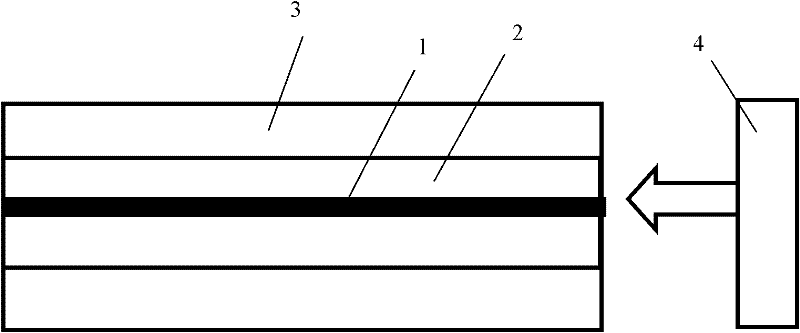
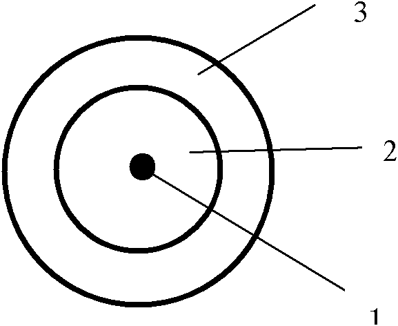
[0014] Embodiment 1, a single-mode amplifier with a large effective mode field area in an active quartz rod, such as figure 1 , 2 , the amplifier includes: an active quartz rod, a pump source 4 . The structure of the active quartz rod is an exposure area 1 , an active quartz rod core 2 and an outer cladding 3 sequentially from inside to outside. The exposure area 1 is located in the center of the active quartz rod, and the refractive index of the exposure area 1, the active quartz rod core 2 and the outer cladding 3 decreases gradually.
[0015] The signal light source inputs the signal light to be amplified from the right end, and uses the pump source 4 to pump the right end surface.
[0016] The refractive index of the exposure area 1 was 1.459, and the radius of the exposure area 1 was 2.5 microns.
[0017] The refractive index of the active quartz rod core 2 is 1.455, and the radius of the active quartz rod core 2 is 5 mm. The refractive index of the outer cladding 3 is 1
Example Embodiment
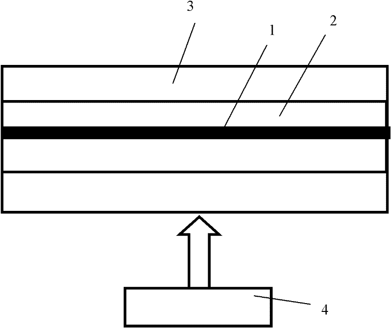
[0018] Embodiment 2, a single-mode amplifier with a large effective mode field area in an active quartz rod with an exposure area, such as image 3 , the amplifier includes: an active quartz rod, a pump source 4 . The structure of the active quartz rod is an exposure area 1 , an active quartz rod core 2 and an outer cladding 3 sequentially from inside to outside. The exposure area 1 is located in the center of the active quartz rod, and the refractive index of the exposure area 1, the active quartz rod core 2 and the outer cladding 3 decreases gradually.
[0019] The signal light source inputs the signal light to be amplified from the right end, and uses the pump source 4 for side pumping.
[0020] The refractive index of the exposure area 1 was 1.457, and the radius of the exposure area 1 was 5 microns.
[0021] The refractive index of the active quartz rod core 2 is 1.454, and the radius of the active quartz rod core 2 is 50 mm. The refractive index of the outer cladding 3 i
Example Embodiment
[0022] Embodiment 3, a single-mode amplifier with a large effective mode field area in an active quartz rod with an exposure area, such as Figure 4 , the amplifier includes: an active quartz rod, a pump source 4 . The structure of the active quartz rod is an exposure area 1 , an active quartz rod core 2 and an outer cladding 3 sequentially from inside to outside. The exposure area 1 is located in the center of the active quartz rod, and the refractive index of the exposure area 1, the active quartz rod core 2 and the outer cladding 3 decreases gradually.
[0023] The signal light source inputs the signal light to be amplified from the right end, uses the pump source 41 for right end face pumping, and uses the pump source 42 for side pumping.
[0024] The refractive index of the exposure area 1 was 1.456, and the radius of the exposure area 1 was 10 microns.
[0025] The refractive index of the active quartz rod core 2 is 1.453, and the radius of the active quartz rod core 2 is
PUM
| Property | Measurement | Unit |
|---|---|---|
| Radius | aaaaa | aaaaa |
| Thickness | aaaaa | aaaaa |
| Radius | aaaaa | aaaaa |
Abstract
Description
Claims
Application Information
 - R&D Engineer
- R&D Manager
- IP Professional
- Industry Leading Data Capabilities
- Powerful AI technology
- Patent DNA Extraction
Browse by: Latest US Patents, China's latest patents, Technical Efficacy Thesaurus, Application Domain, Technology Topic.
© 2024 PatSnap. All rights reserved.Legal|Privacy policy|Modern Slavery Act Transparency Statement|Sitemap