Water discharging device for vacuum tank

A drainage device and vacuum tank technology, applied in the container discharge method, container filling method, gas/liquid distribution and storage, etc., can solve the problems of high failure rate, poor water absorption and drainage effect, high energy consumption, etc., and reach the failure rate Low, improve drainage effect, low energy consumption

Inactive Publication Date: 2014-02-26
SUZHOU FU SHUN PACKING PROD CO LTD
View PDF5 Cites 2 Cited by
  • Summary
  • Abstract
  • Description
  • Claims
  • Application Information

AI Technical Summary

Benefits of technology

This patented technology allows for better drainages by designing an improved drainaging device for use on a vacuumsurge tank. It uses two different types of pipes - external ones called the water store tank (WSC) and internal ones called compressed gas or environment-controlled space. When there're no rainwater from inside the WSC, some parts of this stored liquid will flow out into another part where other liquids may also enter without being able to get ridged during normal operation due to gravity. By connecting these separate components together at their ends, the drier than previous devices was achieved while still allowing them to function properly even if they were damaged over time. Overall, this innovative solution provides more efficient and effective drainings systems for vacuuming tanks.

Problems solved by technology

This patented problem addressed by the present inventors relates to improving the performance of conventional vacuums due to their use of drainable structures like drains made from metal tubings. These designs are expensive but also require regular maintenance over time which can lead to increased costs associated with downtime. Additionally, these solutions may result in low efficiency when they work properly at lower pressures than usual.

Method used


Image

  • Water discharging device for vacuum tank
  • Water discharging device for vacuum tank

Examples


Embodiment 1

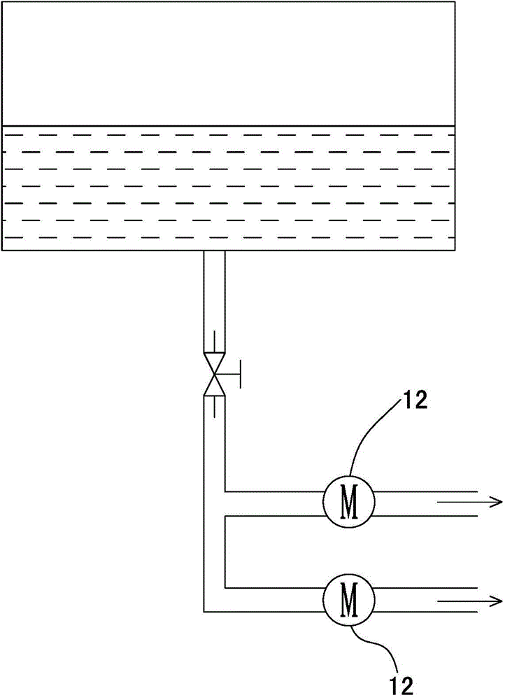
[0027] see figure 2 As shown, a drainage device for a vacuum tank includes a water storage tank 1, the top of the water storage tank is provided with a connecting pipe 2, a first ventilation pipe 3 and a second ventilation pipe 4, and the bottom of the water storage tank is provided with a drainage tube 5;

[0028] One end of the connecting pipe communicates with the bottom of the vacuum tank, so that the bottom of the vacuum tank communicates with the water storage tank; the connecting pipe is provided with a first valve 6;

[0029] One end of the second ventilation pipe communicates with the top of the vacuum tank, so that the top of the vacuum tank communicates with the water storage tank; the second ventilation pipe is provided with a second valve 7;

[0030] One end of the first ventilation pipe is arranged on the top of the water storage tank, and the other end communicates with compressed air or the atmosphere; the first ventilation pipe is provided with a pressure reduc


PUM


Abstract

The invention discloses a water discharging device for a vacuum tank. The water discharging device comprises a water storage tank, wherein the top of the water storage tank is provided with a communicating pipe, a first venting pipe and a second venting pipe, and the bottom of the water storage tank is provided with a water discharging pipe; one end of the communicating pipe is communicated with the bottom of the vacuum tank, so that the bottom of the vacuum tank is communicated with the water storage tank; one end of the second venting pipe is communicated with the top of the vacuum tank, so that the top of the vacuum tank is communicated with the water storage tank; one end of the first venting pipe is arranged at the top of the water storage tank, and the other end of the first venting pipe is communicated with compressed air or atmosphere. The water discharging device disclosed by the invention has the advantages that water in the vacuum tank is collected by utilizing the water storage tank, then the first venting pipe is connected outside, and when the water in the water storage tank is discharged, the pressure in the water storage tank can reach the atmospheric pressure or exceed the atmospheric pressure by the first venting pipe, so that the difficulty of bad water discharge under negative pressure in the prior art is solved and the water discharging effect is greatly improved.

Description


Claims


Application Information

Patent Timeline
Owner SUZHOU FU SHUN PACKING PROD CO LTD
Why Eureka
Try Eureka