Automatic feeding system of rotary evaporator

A rotary evaporator, automatic feeding technology, applied in control/regulation systems, instruments, non-electric variable control, etc., can solve problems such as heavy workload, increase labor costs, etc., to achieve automation, save time and labor costs.

Inactive Publication Date: 2014-12-10
郑旭
View PDF7 Cites 0 Cited by
  • Summary
  • Abstract
  • Description
  • Claims
  • Application Information

AI Technical Summary

Benefits of technology

The technical feature described in this patented technology allows for efficient use of resources during chemical reactions that require heat transfer between two fluids or liquors. It includes systems with sensors to monitor both recoverable and non-recovered solutions from vapour condensers (VCOs). These systems are able to detect if there has been enough material added without stopping their rotation completely, which helps ensure safety while completing the addition process.

Problems solved by technology

This patented technical problem addressed by the present inventors relates to improving the efficiency and ease at which a rotor vaporizer used for evaporation purposes has been able to automatically add solutions when needed without requiring human intervention.

Method used


Image

  • Automatic feeding system of rotary evaporator
  • Automatic feeding system of rotary evaporator

Examples


Embodiment Construction

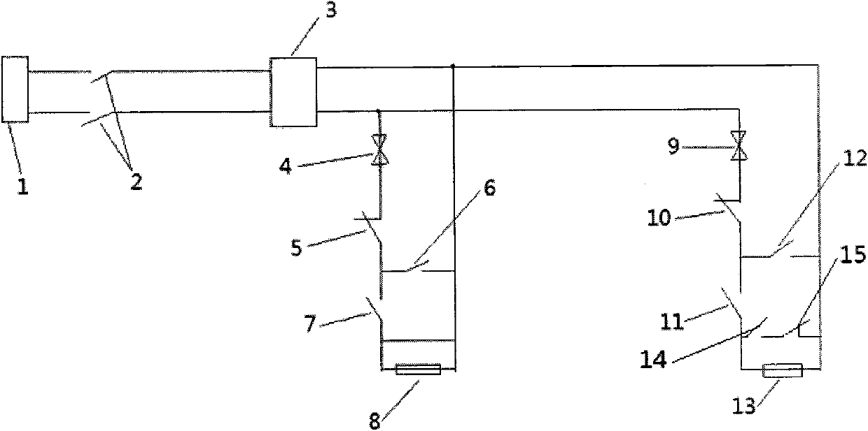
[0010] see figure 1 , figure 2 , an automatic feeding system for a rotary evaporator, this system includes a circuit breaker 2, a switching power supply 3, a first solenoid valve 4, a first liquid level switch 5, a second liquid level switch 6, a first normally open contact 7, a second A relay coil 8 , a second solenoid valve 9 , a third liquid level switch 10 , a fourth liquid level switch 11 , a second normally open contact 12 , a second relay coil 13 , a rotary switch 14 , and a normally closed contact 15 .

[0011] The circuit breaker 2 is connected to the AC power supply 1, and the circuit breaker 2 is also connected to the switching power supply 3. The first solenoid valve 4, the first liquid level switch 5, the first normally open contact 7, the first relay coil 8 and the switching power supply 3 The first circuit is formed in series, and the second liquid level switch 6 is connected in parallel with the first normally open contact 7 and the first relay coil 8 .

[0012


PUM


Abstract

The invention discloses an automatic feeding system of a rotary evaporator. The automatic feeding system of the rotary evaporator is characterized by comprising breakers (2), a switch power source (3), a first electromagnetic valve (4), a first liquid level switch (5), a second liquid level switch (6), a first normally open contact (7), a first relay coil (8), a second electromagnetic valve (9), a third liquid level switch (10), a fourth liquid level switch (11), a second normally open contact (12), a second relay coil (13), a rotary switch (14) and a normally closed contact (15). The automatic feeding system is capable of automatically feeding solution to be evaporated and releasing evaporated solvent, feeding and releasing process is effectively controlled, and time and labor cost are saved.

Description


Claims


Application Information

Patent Timeline
Owner 郑旭
Why Eureka
Try Eureka