Hydraulic lifting rotation device for X-ray imaging detection

An imaging detection and hydraulic lifting technology, which is applied in the direction of supporting machines, mechanical equipment, machine platforms/supports, etc., can solve the problems of large volume of power transmission and transformation equipment, complex internal structure, unsatisfactory height and angle photo effects of auxiliary devices, etc.

Inactive Publication Date: 2015-06-10
STATE GRID CORP OF CHINA +1
View PDF7 Cites 9 Cited by
  • Summary
  • Abstract
  • Description
  • Claims
  • Application Information

AI Technical Summary

Problems solved by technology

However, due to the large volume of power transmission and transformation equipment, the internal structure is relatively complex and other factors have brought many difficulties to the application of this technology in the field.
[0003] At present, the biggest problem faced by the application of this technology i

Method used


Image

  • Hydraulic lifting rotation device for X-ray imaging detection

Examples


Embodiment Construction

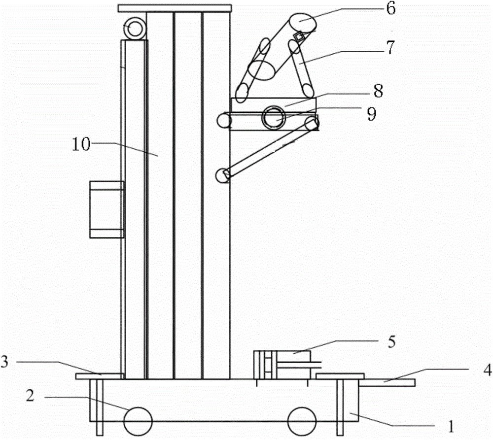
[0011] Such as figure 1 As shown, the present invention is a hydraulic lifting and rotating device for X-ray imaging detection, including a platform base 1, a moving roller 2 is installed on the bottom of the platform base 1, and a foldable The bottom leg 3 is equipped with a lifting column 10 on the platform base 1, and a lifting and rotating platform 8 is installed on the lifting column 10. The lifting and rotating platform 8 is connected with the hydraulic mechanism 5 on the platform base 1 so that it can move along the The lifting column 10 rises or falls, and an X-ray machine support 7 is also installed on the lifting rotary platform 8, and an X-ray transmitter 6 (X-ray machine) is installed on the X-ray machine support 7.

[0012] Among them, a pulling handle 4 is installed on the platform base 1, and the lifting and rotating platform 8 is also connected with the motor through a rotating transmission mechanism, so that it can rotate around the lifting column 10. In addition


PUM


Abstract

The invention relates to a hydraulic lifting rotation device for X-ray imaging detection. The hydraulic lifting rotation device is characterized by comprising a platform base (1), wherein moving idler wheels (2) are mounted at the bottom of the platform base (1); foldable bottom supporting legs (3) are also mounted on the platform base (1); a lifting column (10) is mounted on the platform base (1); a lifting rotation platform (8) is mounted on the lifting column (10) and is connected with a hydraulic mechanism (5) on the platform base (1) so as to move up and down along the lifting column (10); an X-ray emitter bracket (7) is also mounted on the lifting rotation platform (8); an X-ray emitter (6) is mounted on the X-ray emitter bracket (7). The hydraulic lifting rotation device can serve as a convenient and quick bracket for a movable height-adjustable/angle-adjustable X-ray emitting device. The efficiency and the convenience of the X-ray imaging detection of field power equipment are improved.

Description


Claims


Application Information

Patent Timeline
Owner STATE GRID CORP OF CHINA
Why Eureka
Try Eureka