Device for printing laser crystal cooling heat sinks and method thereof

A technology of laser crystals and heat sinks, which is applied to lasers, laser components, phonon exciters, etc., can solve problems such as poor contact, high processing costs, and poor heat dissipation and cooling effects, so as to improve heat dissipation effects, avoid pollution, Ensure consistent thickness

Inactive Publication Date: 2015-08-05
LASER FUSION RES CENT CHINA ACAD OF ENG PHYSICS
View PDF7 Cites 3 Cited by
  • Summary
  • Abstract
  • Description
  • Claims
  • Application Information

AI Technical Summary

Benefits of technology

This patented describes an improved method for creating a tightly fitting interface between a laser device's (lasers) crystals and its housing without leaving residue or other impurities that could affect their performance. It involves direct printting onto the surfaces of these devices with special materials like copper foil instead of traditional methods such as lithography. Additionally, it suggests using different types of motors to control both rotation and movement during scanning to improve thermal management efficiency while minimizing damage from particles caused by external factors like dust. Overall, this new approach simplifies manufacturing processes and enhances overall functionality of the equipment being used.

Problems solved by technology

This patented technical solution described involves improving the performance of an optical device called LMX (Laser Microscope X) used during researches involving laser excitation sources such as Yb:YAG (yellow gallium garnet), Er:Glass (erbium glass). These devices use highly reflective surfaces made of materials like gold plating or aluminum foil to efficiently absorb excess energy generated through laser irradiation. To prevent damage caused by these absorbing layers, the manufacturing processes require precise alignment with other components within specific dimensions. Additionally, current methods involve complicated steps requiring expensive machining tools and long periods of production times.

Method used


Image

  • Device for printing laser crystal cooling heat sinks and method thereof
  • Device for printing laser crystal cooling heat sinks and method thereof

Examples


Embodiment 1

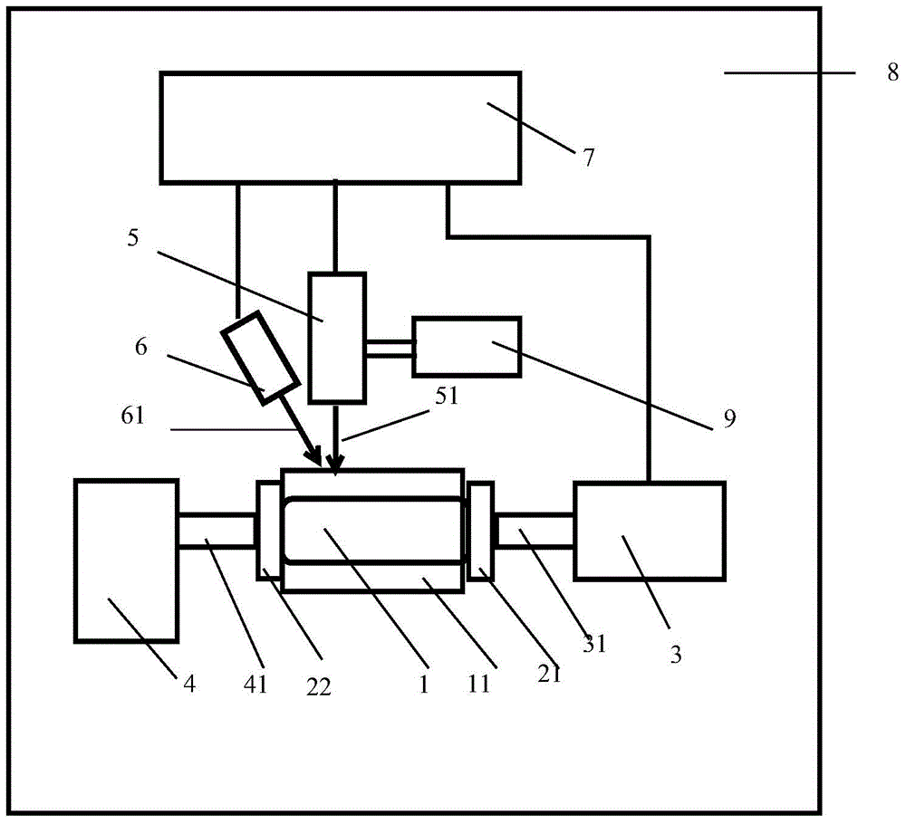
[0035] Such as figure 1 As shown, a device for printing a laser crystal cooling heat sink includes a workbench 8, a laser crystal 1, a first clamp 21, a second clamp 22, a second support block 4, a first motor 3, a second motor 9, a laser 5. Powder feeder 6 and control module 7. The second support block 4, the first motor 3, the second motor 9 and the laser 5 are all fixedly connected to the surface of the workbench 8, the laser crystal 1 is cylindrical, and the first clamp 21 and the second clamp 22 are cylindrical, respectively against On both ends of the laser crystal 1, the area of ​​the abutting surface of the first fixture 21 is larger than the area of ​​the end surface of the laser crystal 1 abutting against it, and the area of ​​the abutting surface of the second fixture 22 is larger than the area of ​​the end surface of the laser crystal 1 abutting against it. The two faces of the fixture that are against the laser crystal completely cover the two end faces of the laser

Embodiment 2

[0044]When printing the cooling heat sink on the surface of the sheet-shaped laser crystal 1, the same part as the embodiment (1) will not be repeated, the difference is: the first motor 3 is not needed, and the third motor is fixedly connected to the laser 5 side. The three motors are connected to the control module 7, and the third motor drives the laser 5 to move in a plane perpendicular to the workbench 8. The sheet-shaped laser crystal 1 is placed perpendicular to the workbench 8, and the surface of the cooling heat sink 11 that needs to be printed faces the laser 5 . The laser beam 51 forms a "back" path on the surface of the laser crystal 1 .


PUM


Abstract

The invention discloses a device for printing laser crystal cooling heat sinks and a method thereof. The device comprises the components of a worktable, a laser crystal, a clamp, a supporting block, a laser and a powder feeder. The clamp is cylindrical and comprises a first clamp and a second clamp which abut against two ends of the laser crystal. The supporting block is fixedly connected with the worktable and comprises a first supporting block and a second supporting block. The first supporting block abuts against the first clamp. The second supporting block abuts against the second clamp. According to the device and the method of the invention, multiple layers of cooling heat sinks are printed on the surface of the laser crystal through 3D printing technology, thereby realizing close combination between the laser crystal and the cooling heat sinks and remarkably improving heat radiation effect of the cooling heat sinks.

Description


Claims


Application Information

Patent Timeline
Owner LASER FUSION RES CENT CHINA ACAD OF ENG PHYSICS
Why Eureka
Try Eureka