Coupling assembly, motor vehicle power train and coupling control method
A technology for clutches and drive trains, applied in clutches, mechanical equipment, fluid pressure actuators, etc., can solve problems such as high cost and achieve high flexibility
- Summary
- Abstract
- Description
- Claims
- Application Information
AI Technical Summary
Problems solved by technology
Method used
Image

Examples
Example Embodiment
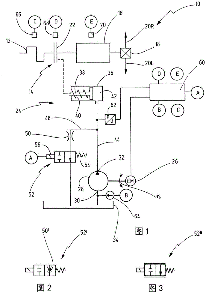
[0060] in figure 1 The drive train for a motor vehicle is shown in schematic form in and is generally designated 10. The drive train 10 has a drive motor 12, which may include an internal combustion engine or a hybrid drive unit. In addition, the power train 10 has a clutch structure 14 which is connected to the drive motor 12 on the input side. The clutch structure 14 is connected to a stepped transmission 16 on the output side, and the stepped transmission can be constructed in an intermediate shaft structure, for example.
[0061] The stepped transmission 16 and the clutch structure 14 may also be formed by a transducer-automatic transmission.
[0062] The output end of the stepped transmission 16 is connected to the differential 18, and the driving power is distributed to the two driven wheels 20L, 20R by means of the differential.
[0063] The clutch structure 14 includes a friction clutch 22, of which, for example, a dry clutch or a wet clutch in the form of a plate clutch may b
PUM
 Abstract
Description
Claims
Application Information
 - R&D Engineer
- R&D Manager
- IP Professional
- Industry Leading Data Capabilities
- Powerful AI technology
- Patent DNA Extraction
Browse by: Latest US Patents, China's latest patents, Technical Efficacy Thesaurus, Application Domain, Technology Topic.
© 2024 PatSnap. All rights reserved.Legal|Privacy policy|Modern Slavery Act Transparency Statement|Sitemap