Sediment sampler

A sampler and bottom mud technology, applied in the direction of sampling devices, etc., to achieve the effect of low sampling conditions, convenient assembly, and prevent sample leakage

Active Publication Date: 2015-11-18
BEIJING WATER SCI & TECH INST
View PDF8 Cites 9 Cited by
  • Summary
  • Abstract
  • Description
  • Claims
  • Application Information

AI Technical Summary

Problems solved by technology

At present, there are various sediment sampling products at home and abroad, but their common disadvantages are that they cannot meet the requirements at the same time: easy operation, no disturbance during sampling; when the sampling tube is lifted, the s

Method used


Image

  • Sediment sampler
  • Sediment sampler
  • Sediment sampler

Examples


Embodiment 1

[0026] Embodiment 1 sediment sampler

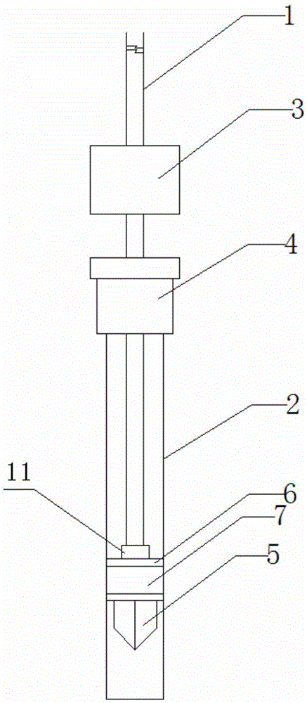
[0027] Such as figure 1 As shown, the sediment sampler is composed of a connecting rod 1, a sampling pipe 2, a gravity hammer 3, a fixed joint under force 4, a piston firmware 5, a piston gasket 6 and a rubber piston 7.

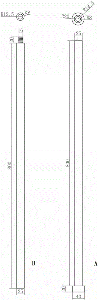
[0028] Such as figure 2 As shown, connecting rod 1 is processed by sampling metal materials. The length is determined according to the sampling depth. It can be directly borrowed from the drilling rod in the survey work. Its main function is to connect the gravity hammer, the fixed joint under force, the piston firmware, the piston gasket, and the rubber piston. , Water sampling at different depths can be realized by connecting and lengthening. The length of each connecting rod is 50cm-100cm, and the number and size of connections are determined according to the depth of the water body. figure 2 A is a single connecting rod, figure 2 B is an extension rod.

[0029] Such as Figure 5 As shown, the stressed fixed joi


PUM

PropertyMeasurementUnit
Diameteraaaaaaaaaa

Abstract

The invention relates to a sediment sampler, which comprises a connection rod, a sampling tube, a gravity hammer, a force fixation joint and a piston assembly, wherein the sampling tube is a transparent tube, one end of the sampling tube is fixedly connected with the force fixation joint, the gravity hammer and the force fixation joint can be slidably sleeved on the outer portion of the connection rod, one end of the connection rod sequentially penetrates through the gravity hammer and the force fixation joint and then extends into the sampling tube, and is fixedly connected with the piston assembly arranged inside the sampling tube, and the piston assembly can slide along the wall of the sampling tube and maintains the air tightness inside and outside of the piston assembly. According to the present invention, the sampler has characteristics of simple structure, low processing price, durability, easy carrying, high use efficiency and good sampling effect, and can be used for sediment sampling with various water body depth ranges in the fields of geology, environmental protection, water conservancy, lakes and the like.

Description


Claims


Application Information

Patent Timeline
Owner BEIJING WATER SCI & TECH INST
Why Eureka
Try Eureka