Complete vehicle road test room vehicle travelling channel device

A technology for vehicle driving and whole vehicle road, which is applied in the direction of measuring device, vehicle testing, machine/structural component testing, etc. The effect of efficiency

Inactive Publication Date: 2016-01-13
BEIJING INST OF STRUCTURE & ENVIRONMENT ENG +1
View PDF6 Cites 2 Cited by
  • Summary
  • Abstract
  • Description
  • Claims
  • Application Information

AI Technical Summary

Benefits of technology

This patented technology allows an apparatus called this system to safely move cars during testing without having them lift up or get damaged from being lifted off their wheels. It also provides versatility with regards to varying car types and configurations that may require support while driving on roads. Additionally, its design makes it easy to install afterward when needed. Overall, these benefits make the process more efficient than traditional methods like tire pressure tests.

Problems solved by technology

This patents describes how reliable and long lasting tests are needed during car manufacturing processes. However, current methods require physical contact between the simulated part or components (such as wheels) and other objects like rails. Additionally, these techniques involve expensive tools used repeatedly over many hours, making them impractical when studying smaller model designs due to their high cost compared to traditional experimental approaches.

Method used


Image

  • Complete vehicle road test room vehicle travelling channel device
  • Complete vehicle road test room vehicle travelling channel device
  • Complete vehicle road test room vehicle travelling channel device

Examples


Embodiment Construction

[0022] The technical solutions of the present invention will be further described below in conjunction with the accompanying drawings.

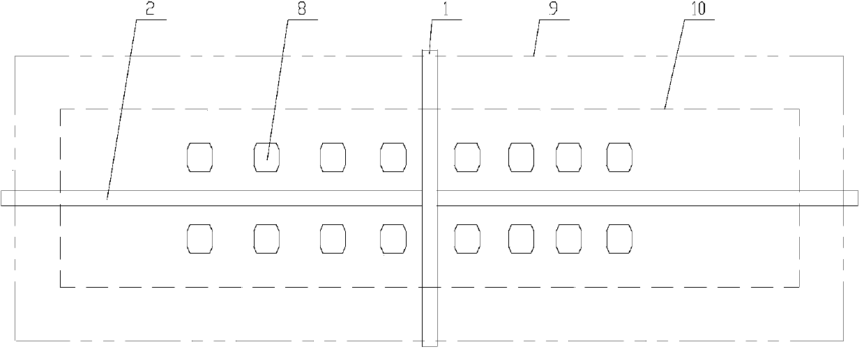
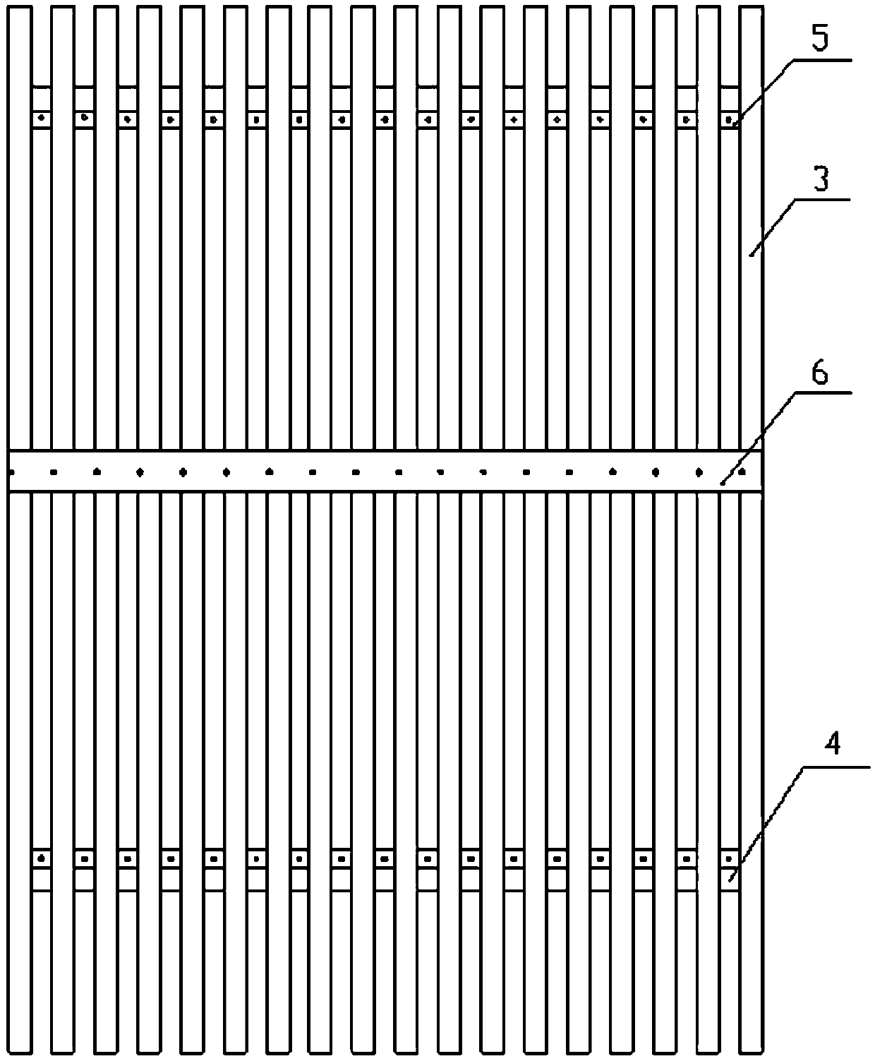
[0023] This embodiment provides a vehicle running channel device for a vehicle road test room, the structure of which is as follows: Figure 1 to Figure 3 As shown, it includes a beam 1 , two longitudinal beams 2 , a plurality of platform modules, an auxiliary cover plate 7 and an actuator 8 .

[0024] The two ends of the crossbeam 1 are directly fixedly installed in the bearing areas on both sides of the pit wall 9. One end of the longitudinal beam 2 is supported by the crossbeam 1, and the other end is supported by the pit wall. The beam 1 and the longitudinal beam 2 can adopt box girder, I-shaped beam or other cross-section types, and are the main load-bearing structure of the device. One end of the platform module is installed on the longitudinal beam 2, and the other end is installed on the pit wall 9, and each platform module is closely a


PUM


Abstract

The invention relates to the field of vehicle road simulation tests, and particularly relates to a complete vehicle road test room vehicle travelling channel device. The technical scheme is that two ends of a cross beam (1) are directly and fixedly installed on a pit wall (9), and two ends of a longitudinal beam (2) are installed on central sections of the pit wall (9) and the cross beam (1) respectively; platform modules are installed between the longitudinal beam (2) and the pit wall (9); an actuator (8) is installed on a ground pit; each platform module comprises a plurality of bearing units (3) which are parallel to each other and a connection component (4); and the connection component (4) is vertical with the bearing units (3) and is fixedly connected with the bearing units (3). The device provided by the invention has the beneficial effects that the cross beam and the longitudinal beam are adopted to construct a main bearing structure of the whole device; a safety channel is provided for a vehicle which is driven to a predetermined position of the test through the platform modules, and a problem that a heavy vehicle is not convenient for hoisting is solved; adjusting requirements of wheels spans and wheel bases of different vehicle are satisfied, and versatility is possessed; the structure is simple, installation and connection are convenient; and the device is suitable for various kinds of road simulation test rooms.

Description


Claims


Application Information

Patent Timeline
Owner BEIJING INST OF STRUCTURE & ENVIRONMENT ENG
Why Eureka
Try Eureka