Strip mounting equipment

A tape and mounting technology, applied in the field of tape mounting equipment, can solve the problems that the tape cannot be clearly expressed, and the structure of the component placement machine cannot be applied, so as to achieve the effect of improving light uniformity.

Active Publication Date: 2016-01-27
HANWHA AEROSPACE CO LTD
View PDF5 Cites 0 Cited by
  • Summary
  • Abstract
  • Description
  • Claims
  • Application Information

AI Technical Summary

Problems solved by technology

[0010] However, unlike electronic components, tapes often have transmissive and reflective properties for lighting, so it is not possible to apply a structure suitable for existing component mounters.
This is because the light transmission and reflectivity of the strips make the strips not clearly expressed in the captured image

Method used


Image

  • Strip mounting equipment
  • Strip mounting equipment
  • Strip mounting equipment

Examples


Example Embodiment

[0043] The advantages, features, and methods used to achieve the objectives of the present invention will be understood with reference to the embodiments described in detail in conjunction with the drawings. However, the present invention is not limited to the embodiments disclosed below. It can be implemented in different forms. The embodiments are only for fully disclosing the present invention and fully telling the scope of the present invention to those in the technical field to which the present invention belongs. Provided by persons with ordinary knowledge, the present invention is only defined by the claims. Throughout the entire specification, the same reference numerals denote the same constituent elements.

[0044] In addition, the aforementioned embodiments will be explained with reference to cross-sectional views and / or schematic diagrams which are idealized example drawings of the present invention. Therefore, the form of the example diagram may be changed according


PUM


Abstract

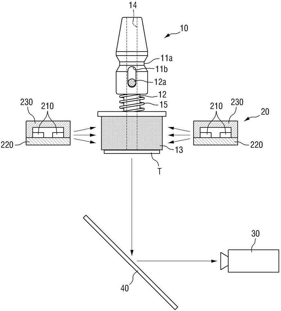
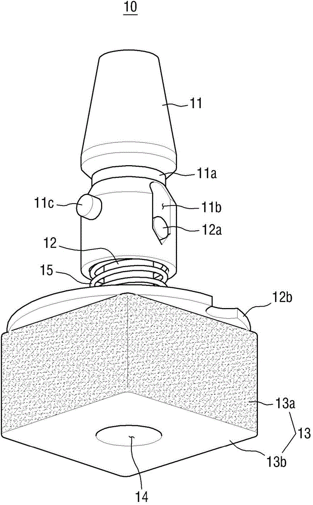
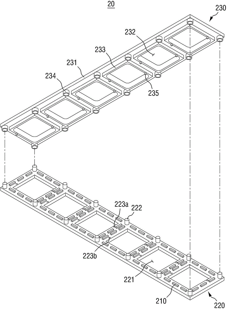
The invention discloses stripe mounting equipment. The equipment comprises an optical filer which comprises at least one pickup hole and a light source arranged to be surrounding the pickup hole and supplies light to the pickup hole, and is used for converting the light supplied by the light source into colored light which is transmitted to the pickup hole; a mounting strip which is supplied in a manner of being adjacent to the pickup hole; a sucking mouth which enters into the pickup hole to absorb the mounting strip and comprises a sucking mouth top, wherein the sucking mouth top emits light through the colored light emitted from the optical filter to the pickup hole; and a camera which photographs the sucking mouth top and absorbs the mounting strip at the sucking mouth top.

Description


Claims


Application Information

Patent Timeline
Owner HANWHA AEROSPACE CO LTD
Why Eureka
Try Eureka