Multi-margin multi-power channel permanent magnetism generator

A permanent magnet generator, multi-power technology, applied in multi-output synchronous motors, synchronous motors with static armatures and rotating magnets, and the shape/style/structure of winding conductors, etc., can solve the problem of high cost, large space, problems such as large weight, to achieve the effect of ensuring output capacity, improving power density, and meeting multi-power and multi-margin requirements

Inactive Publication Date: 2016-03-02
HARBIN DONGAN ENGINE GRP
View PDF3 Cites 2 Cited by
  • Summary
  • Abstract
  • Description
  • Claims
  • Application Information

AI Technical Summary

Problems solved by technology

Large space, heavy weight, high cost, unsuitable for aviation power system requirements

Method used


Image

  • Multi-margin multi-power channel permanent magnetism generator

Examples


Example Embodiment

[0011] Example

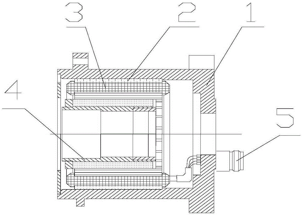
[0012] An aircraft power supply requires power supply for loads with power of 130W and 50W, and the power of 130W has three margins. The specific structure of the permanent magnet motor is:

[0013] The permanent magnet generator includes a stator iron core, a stator winding, a rotor with magnetic poles, and a housing. The stator iron core is installed on the housing and is provided with stator windings. The rotor with magnetic poles is arranged in the stator iron core; on the stator There are uniformly distributed slots, the number of slots Z=3*(n+2m), where Z is the number of slots, n is the number of channels that can meet the output voltage by one winding, and m is the number of channels that need corresponding two windings. The number of channels that can meet the output voltage; after calculation, one winding can meet the power of 50W, but two sets of power are required to meet the power of 130W, so n is 1, m is 3, then Z, that is, the number of slots is 21; al


PUM


Abstract

The invention relates to a multi-margin multi-power channel permanent magnetism generator, comprising a stator iron core (2), a stator winding, a rotor with a magnetic pole and a housing; the stator iron core is installed on the housing and is provided with the stator winding; the rotor with the magnetic pole is arranged inside the iron core; the stator iron core is provided with grooves which are uniformly distributed; the pitch of the stator winding is 1; the number of the grooves for each phase and each pole is 0.5; the coil turns, the winding number and the coil winding diameter are set according to the regular method and the output power of the channel; and the leading out wire of the stator winding is connected to a socket on the housing. The invention satisfies the requirement for multi-power and multi margin, fully utilizes the volume of the motor and guarantees the output capability of the motor.

Description


Claims


Application Information

Patent Timeline
Owner HARBIN DONGAN ENGINE GRP
Why Eureka
Try Eureka