Electric self-locking type contactor

A self-locking, contactor technology, applied in the direction of relays, electrical components, electromagnetic relays, etc., can solve the problems of wasting power resources, failure of power failure, etc., and achieve the effect of unique structure and convenient use

Active Publication Date: 2016-10-12
TRUST TECH SHANGHAI
View PDF5 Cites 2 Cited by
  • Summary
  • Abstract
  • Description
  • Claims
  • Application Information

AI Technical Summary

Benefits of technology

The technology described in this patented solves problems with current switches that have an automatic lock mechanism but it also makes them difficult for people who are unskilled at handling them due to their lack of intuitive understanding or ability to operate these devices effectively themselves. This results from its own design features such as a special spring used instead of traditional mechanisms like buttons on existing switches.

Problems solved by technology

In this patented technology, there are two types of contacts: Contacts that work with electricity without relying on any external energy sources like batteries or AC signals for their operation; These ContactSes can be used at home or factory settings where they shouldn't have them constantly connected when needed. However, these methods were developed over time by different companies due to various factors such as cost savings, environmental concerns, etc., which led researchers into finding ways to improve upon how current Electrification Connections (ECC) works more efficiently while reducing wasteful usage of power resources.

Method used


Image

  • Electric self-locking type contactor
  • Electric self-locking type contactor
  • Electric self-locking type contactor

Examples


Embodiment Construction

[0012] The present invention will be further described below in conjunction with specific embodiments. The exemplary embodiments and descriptions of the present invention are used to explain the present invention, but not as a limitation to the present invention.

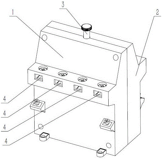
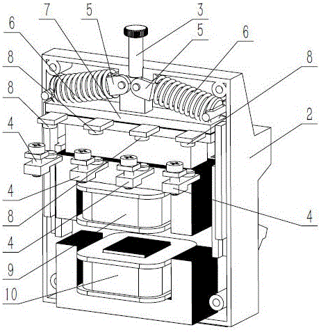
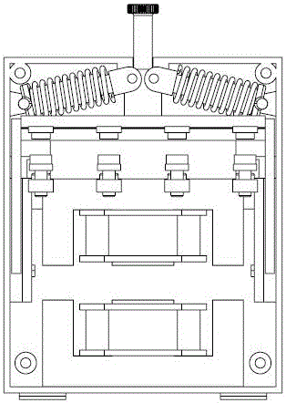
[0013] Such as figure 1 , figure 2 , Figure 5 As shown, an electrical self-locking contactor includes a housing, a manual handle 3, two self-locking levers 5, two self-locking springs 6, a sliding connecting plate 7, eight terminals 4, and a sliding electromagnet 9 And fixed electromagnet 10, it is characterized in that: described casing comprises front casing 1 and rear casing 2, and front casing 1 and rear casing 2 are mutually symmetrically connected by screw; Described fixed electromagnet 10 is installed on The lower position inside the housing; the manual handle 3 slides up and down and is installed at the upper position inside the housing. The other ends of 5 are respectively hingedly mounted on the lower pa


PUM


Abstract

The invention discloses an electric self-locking type contactor which comprises a shell, a manual handle, two self-locking rods, two self-locking springs, a sliding connecting plate, eight wiring terminals, a sliding electromagnet, and a fixed electromagnet. The shell comprises a front shell and a back shell. The fixed electromagnet is installed at the lower part in the shell. The manual handle is installed at the upper part in the shell in a vertical sliding way. One end of each of the two self-locking rods is hinged to a side of the upper part in the shell, and the other end of each of the two self-locking rods is hinged to the lower part of the manual handle. The two self-locking springs sleeve the two self-locking rods. The sliding connecting plate is installed at the upper part in the shell, and the central position of the upper part of the sliding connecting plate is installed at the lower end of the manual handle. The sliding electromagnet is installed under the sliding connecting plate. Each of the wiring terminals is provided with a fixed contact. According to the invention, through arranging the self-locking springs, the purpose of contactor mechanical self locking is realized, the structure is unique, and the electric self-locking type contactor is convenient to use.

Description


Claims


Application Information

Patent Timeline
Owner TRUST TECH SHANGHAI
Why Eureka
Try Eureka