Automatic control dispersing valve

The technology of a batching box and a control panel is applied in the field of automatic control batching valve, which can solve the problems of increasing the cost of wind turbine blade equipment, reducing production efficiency, and high manufacturing cost, and achieving the effects of easy promotion, reduced manufacturing cost, and simple and convenient operation.

Inactive Publication Date: 2017-04-26
SHANDONG UNIV OF TECH
View PDF5 Cites 4 Cited by
  • Summary
  • Abstract
  • Description
  • Claims
  • Application Information

AI Technical Summary

Problems solved by technology

Although the function can be realized, due to the complex structure and high manufacturing cost, the cost of manufacturing wind turbine blade equipment is increased, and the production efficiency is re

Method used


Image

  • Automatic control dispersing valve

Examples


Embodiment Construction

[0012] The following will clearly and completely describe the technical solutions in the embodiments of the present invention with reference to the accompanying drawings in the embodiments of the present invention. Obviously, the described embodiments are only some, not all, embodiments of the present invention.

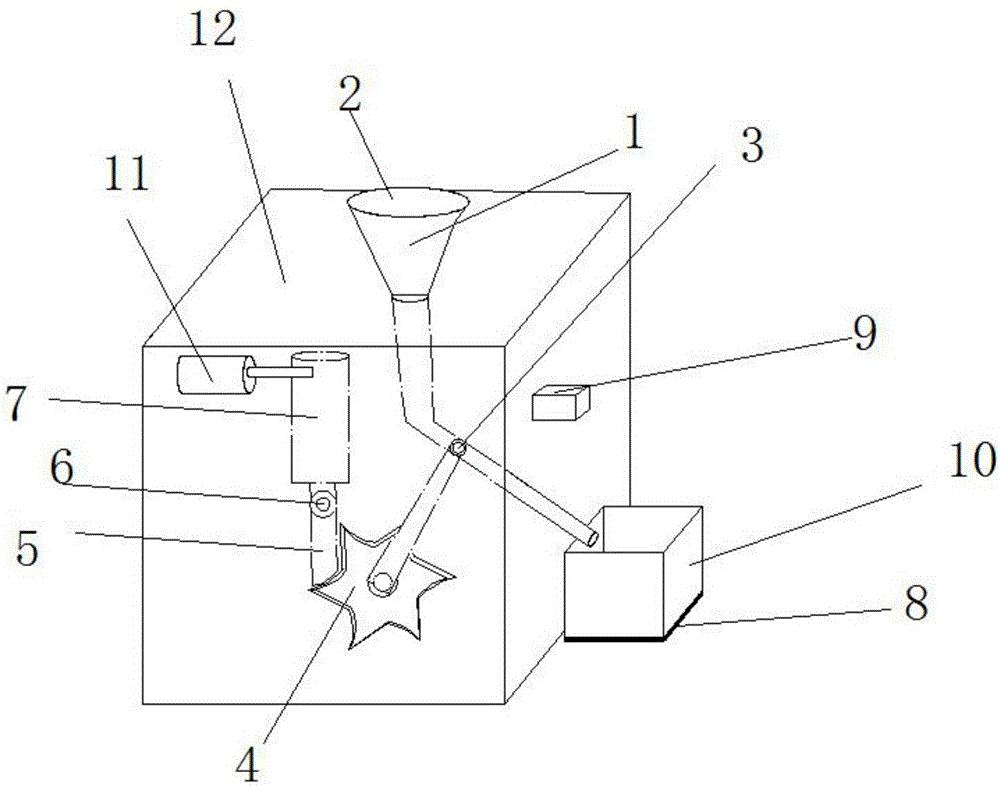
[0013] refer to figure 1 , an automatic control batching valve, including a housing 12, the top of the housing 12 is provided with a feed end 1, and one side of the feed end 1 is interference-connected with an end cover 2, and the bottom of the feed end 1 is connected with an inlet The feeding pipe, the feeding pipe extends out of the outer wall of the housing 12, and the inner wall of the feeding pipe is connected with a spool 3, the spool 3 is a cylinder, and the axis of the spool 3 is provided with a through hole, and the spool 3 passes through Crankshaft is connected with ratchet 4, and one side of ratchet 4 is provided with ratchet 5, and ratchet 5 is connected wit


PUM


Abstract

The invention discloses an automatic control dispersing valve which comprises a shell. A feeding end is arranged at the top of the shell. One end of the feeding end is in interference connection with an end cover. A feeding pipe is connected below the feeding end. The feeding pipe extends out of the outer wall of the shell. A valve element is connected to the inner wall of the feeding pipe. The valve element is a cylinder, and a through hole is formed in the axis of the valve element. According to the automatic control dispersing valve, an air pump is used for inflating an air cylinder to serve as power, the linear reciprocating movement of the air cylinder is converted into one-direction intermittent rotation of a pawl, the pawl pushes a ratchet wheel to rotate, the ratchet wheel is connected with the valve element, and therefore the position of the through hole in the valve element is adjusted to achieve feeding and feeding closing. According to the design, the structure is reasonable and simple, noise pollution is lowered, meanwhile, electric power serves as cleaning energy, secondary pollution caused by using a diesel engine and a gasoline engine is avoided, a pressure sensor and a control panel are matched with an air pump, automatic control can be achieved through the arrangement of the control panel, operation is simple and convenient, the manufacturing cost is greatly lowered, great practicability is achieved, and popularization is easy.

Description


Claims


Application Information

Patent Timeline
Owner SHANDONG UNIV OF TECH
Why Eureka
Try Eureka