Super-resolution image quality evaluation method

A low-resolution image and super-resolution technology, which is applied in the field of super-resolution image quality evaluation, can solve problems such as time-consuming, subjective experiments consume money, and cannot be embedded in super-resolution algorithms, and achieve high correlation effects

Active Publication Date: 2017-05-24
方玉明
View PDF4 Cites 12 Cited by
  • Summary
  • Abstract
  • Description
  • Claims
  • Application Information

AI Technical Summary

Benefits of technology

This technology uses different techniques for calculating differences between two types of data - images or features like roughness on surfaces. By analyzing these variations, we can determine how well an object looks at them compared against another person's own skin tone.

Problems solved by technology

This patented technical problem addressed in this patents relates to improving the accuracy and efficiency of image resolution techniques that use super-microscopies (SM) technique. Current interpolating methodologies result in edges and noise when analyzed at higher frequencies than traditional ones. Objectivity tests like Support Vector Regression and Deep Learning provide qualitatively assessment tools for understanding how well an SM process works over large amounts of data.

Method used


Image

  • Super-resolution image quality evaluation method
  • Super-resolution image quality evaluation method
  • Super-resolution image quality evaluation method

Examples


Embodiment Construction

[0041] The technical solutions of the present invention will be described in further detail below in conjunction with the accompanying drawings.

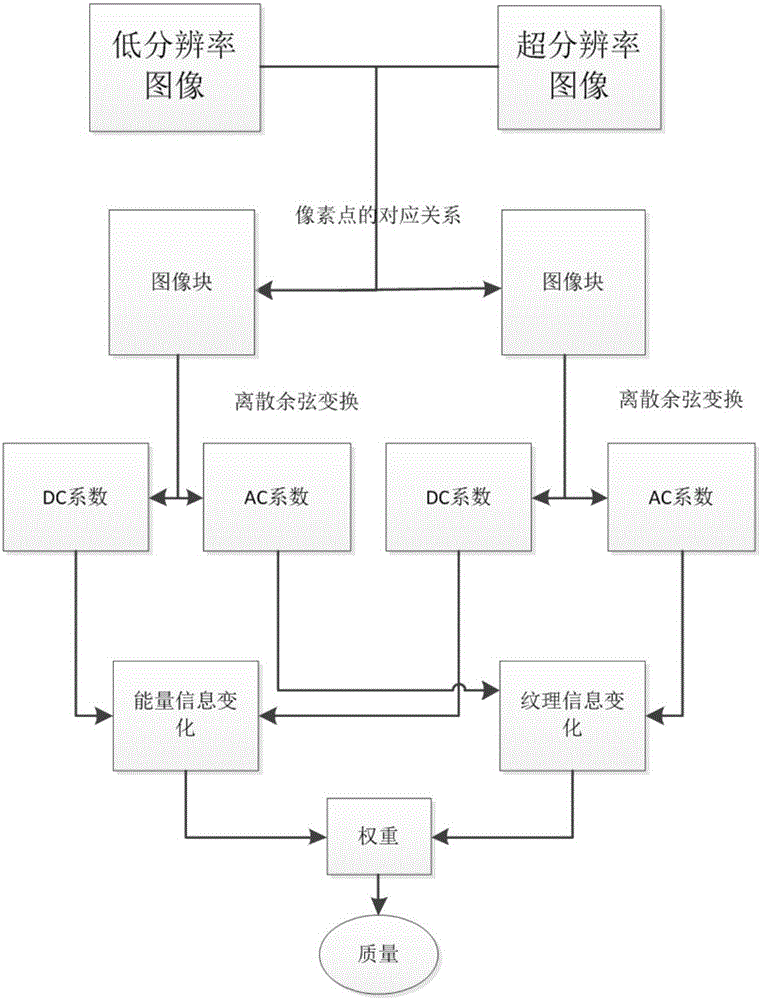
[0042] The process of the present invention is as figure 1 As shown, it includes the following steps:

[0043] Step 1: Establish the corresponding relationship between local image blocks. According to the local positional relationship between the low-resolution image and the super-resolution image, the image block corresponding relationship between the low-resolution image and the super-resolution image is obtained. The size of the low-resolution image can be expressed as i*j, i represents the number of rows of the low-resolution image, and j represents the number of columns of the low-resolution image; the size of the super-resolution image can be expressed as (k*i)*( k*j), k>1, k*i represents the number of rows of the super-resolution image, and k*j represents the number of columns of the super-resolution image. Take an image patc


PUM


Abstract

The present invention relates to a super-resolution image quality evaluation method. The method comprises: employing a pixel corresponding relation between a low-resolution image and a super-resolution image to obtain a corresponding relation between local image blocks, respectively solving the energy and the texture information of the low-resolution image and the super-resolution image, and obtaining the vision similarity between the changing of the two features. The final super-resolution image quality is obtained through evaluation of the vision similarity of the local image blocks of the low-resolution image and the super-resolution image. The experiment result shows good effects in the quality evaluation of the super-resolution image.

Description


Claims


Application Information

Patent Timeline
Owner 方玉明
Why Eureka
Try Eureka