Electro-hydraulic control pressure shutoff system and method used for hydraulic support vertical column

A hydraulic support column, electro-hydraulic control technology, applied in the mine roof support, pillar/support, earthwork drilling and mining, etc., can solve the dismantling torque that cannot meet the guide sleeve of the middle cylinder, power loss of the hydraulic motor of the column dismantling machine, dismantling Low work efficiency and other problems, to achieve the effect of improving the success rate of disassembly, solving safety accidents, and improving disassembly efficiency

Active Publication Date: 2017-08-22
CHINA SHENHUA ENERGY CO LTD +1
View PDF5 Cites 2 Cited by
  • Summary
  • Abstract
  • Description
  • Claims
  • Application Information

AI Technical Summary

Benefits of technology

This patented technology allows for easy maintenance or replacement of tools inside an oil supporting apparatus without having to shut down its operation completely when replacing parts that may be damaged due to damage from excessive force on equipment. It achieves this by controllably adjustable fluid passages within certain structures called chambers where liquids circulate between them. By doing these movements, the hydrostatic pressure applied to each chamber gradually increases until they reach their desired level. Once all necessary fluids have been filled into the chambrals, the pump continues operating even if there's any leakiness around those channels.

Problems solved by technology

This patented describes an apparatus called a Vertical Column Displacement Machine (VCDM) used during the maintenance of hydrous support columns on full mechanical mineralization works. However, current methods require complete removal from these machines before they can continue operating effectively due to issues such as excessive friction between the inner and outside surfaces when rotating the parts inside them. Additionally, there may still remain some debris left behind after removing certain components by screw fasteners, making this task difficult without causing damage.

Method used


Image

  • Electro-hydraulic control pressure shutoff system and method used for hydraulic support vertical column
  • Electro-hydraulic control pressure shutoff system and method used for hydraulic support vertical column
  • Electro-hydraulic control pressure shutoff system and method used for hydraulic support vertical column

Examples


Embodiment Construction

[0020] The technical solutions of the present invention will be described in detail below in conjunction with the accompanying drawings and specific embodiments.

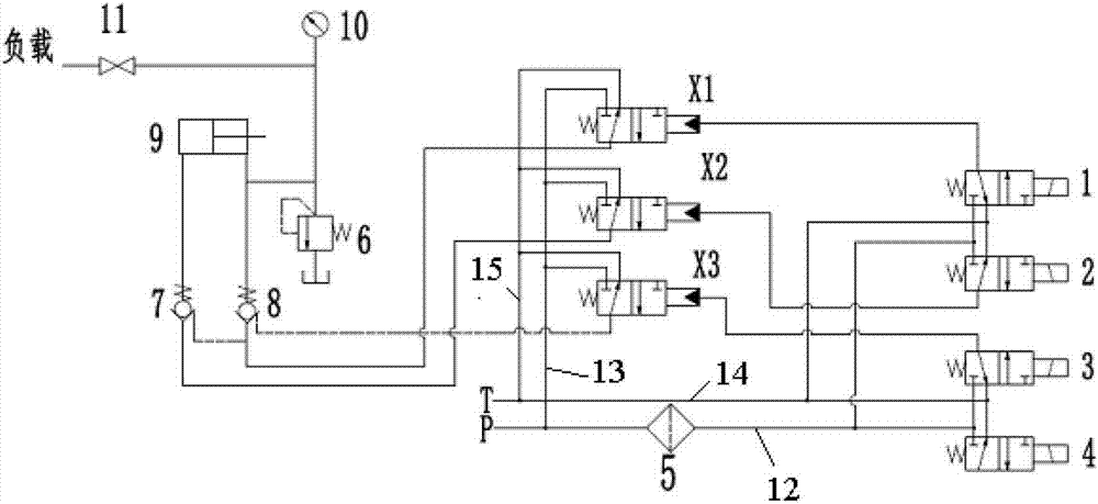
[0021] figure 1 It shows the control principle diagram of the electro-hydraulic control pressure holding system of the embodiment of the present invention, as figure 1 As shown, the electro-hydraulic control pressure holding system includes the main liquid inlet pipeline P, the main liquid return pipeline T, the supercharger 9, the first hydraulic control check valve 8, the second hydraulic control check valve 7, the first hydraulic control two-way One-position three-way reversing valve X1, the second hydraulically controlled two-position three-way reversing valve X2, the first electromagnetic reversing valve 1 and the second electromagnetic reversing valve 2.

[0022] Wherein, the main liquid inlet pipeline P includes a first branch 12 and a second branch 13 . The main liquid return pipeline T includes a third branc


PUM


Abstract

The embodiment of the invention discloses an electro-hydraulic control pressure shutoff system used for a hydraulic support vertical column. The electro-hydraulic control pressure shutoff system comprises a liquid inlet main pipeline, a liquid returning main pipeline, a pressurizer, two hydraulic control one-way valves, two hydraulic control two-position three-way reversing valves and two electromagnetic reversing valves. The liquid inlet main pipeline comprises a first branch and a second branch; the liquid returning main pipeline comprises a third branch and a fourth branch; the first branch is connected with inlets of the two electromagnetic reversing valves; emittings of the two electromagnetic reversing valves are connected with control openings of the two hydraulic control two-position three-way reversing valves; oil returning openings of the two electromagnetic reversing valves are connected with the third branch; the second branch is connected with inlets of the two hydraulic control two-position three-way reversing valves; oil returning openings of the two hydraulic control two-position three-way reversing valves are connected with the fourth branch; and an emitting of the pressurizer used for being connected with an annular cavity. The embodiment of the invention discloses an electro-hydraulic control pressure shutoff method used for the hydraulic support vertical column. By utilizing the electro-hydraulic control pressure shutoff system and method used for the hydraulic support vertical column, the disassembling efficiency of a middle cylinder guide sleeve can be improved.

Description


Claims


Application Information

Patent Timeline
Owner CHINA SHENHUA ENERGY CO LTD
Why Eureka
Try Eureka