System and method for monitoring state of mudguard

A state monitoring device and state data technology, applied in radio wave measurement systems, signal transmission systems, satellite radio beacon positioning systems, etc., can solve problems such as errors, unfavorable maintenance, complex wiring, etc., to reduce construction costs and build Difficulty, improving flexibility and practicability, and the effect of flexible layout

Pending Publication Date: 2017-11-10
CHINA JILIANG UNIV
View PDF7 Cites 0 Cited by
  • Summary
  • Abstract
  • Description
  • Claims
  • Application Information

AI Technical Summary

Benefits of technology

This patented technology allows wireless communication between collector devices (sensor) with sensors attached thereto without requiring complex cabling arrangements that could increase costs and difficulties associated therewith. It also makes maintenance tasks simpler than traditional systems due to its ability to select multiple detectable locations on the sensor surface instead of having all these fixed ones at once. Overall this results in improved efficiency and versatility in various applications such as environmental science researches where remote measurements may require frequent changes over different areas within an area being studied.

Problems solved by technology

This patented technical problem addressed in this patents relates to how well an oil field facility's soil holding fabric (SRT) should keep clean when exposed to high levels of sea saltwater while still maintaining their function effectively without causing damage caused by excessive movement that could affect other parts of the equipment.

Method used


Image

  • System and method for monitoring state of mudguard
  • System and method for monitoring state of mudguard
  • System and method for monitoring state of mudguard

Examples


Embodiment 1

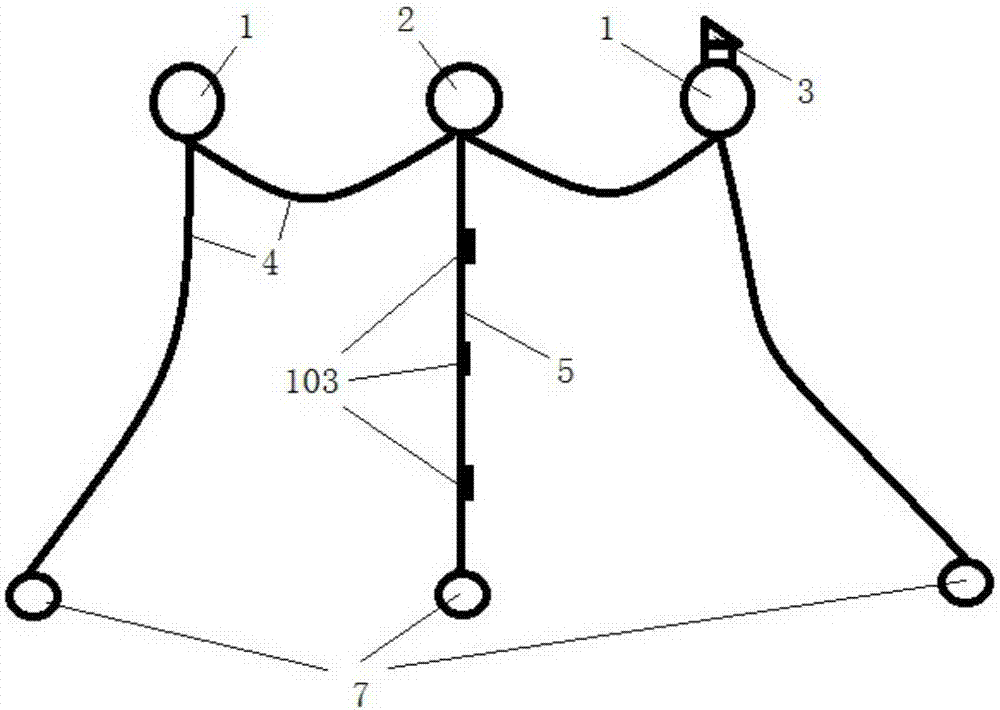
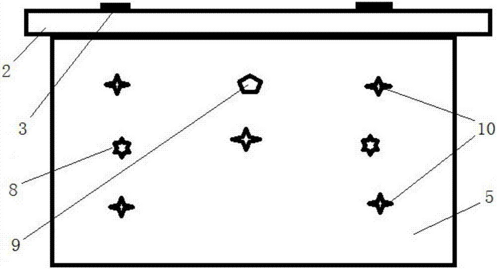
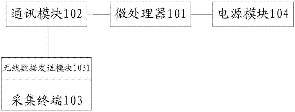
[0042] This embodiment provides a kind of mudguard cloth condition monitoring device, such as Figure 1 to Figure 4 As shown, the mudguard condition monitoring device includes a microprocessor 101 , a communication module 102 connected to the microprocessor 101 , a plurality of collection terminals 103 and a power supply module 104 . A plurality of collection terminals 103 are distributed on the mudguard cloth, and communicate with the microprocessor 101 in a wireless manner.

[0043]Each collection terminal 103 is provided with a wireless data sending module 1031 . The collection terminal 103 sends the detected mudguard status data to the microprocessor 101 through the wireless data sending module 1031 . The microprocessor 101 receives the mudguard status data from the acquisition terminal 103 through the communication module 102, and transmits the received mudguard status data to the remote server through the communication module 102, or, the microprocessor 101 is responsible

Embodiment 2

[0058] This embodiment provides a kind of mudguard cloth state monitoring system, such as Image 6 As shown, the mudguard condition monitoring system includes the mudguard condition monitoring device 100 and the remote server 200 described in the first embodiment above.

[0059] The remote server 200 includes a central processing unit 201 , a second communication unit 202 connected to the central processing unit 201 and an alarm 203 . The second communication unit 202 is used to receive the mudguard status data transmitted by the mudguard status monitoring device, and transmit the mudguard status data to the central processing unit 201 . The central processing unit 201 is used for sending an alarm signal to the alarm device 203 and starting the alarm device 203 to give an alarm when the received mudguard cloth state data exceeds the set safety range.

[0060] The second communication unit 202 is set corresponding to the first communication unit 1022 in the mudguard condition mon


PUM


Abstract

The invention provides a device and system for monitoring the state of a mudguard. Data acquisition terminals and a microprocessor transmit data mutually in a wireless manner, so that lots of complicated wiring is avoided, the flexibility and practicability of the device are improved, the device construction cost and construction difficulty are reduced, and the staff can carry out maintenance and repairing conveniently. A need of selecting more detection points is met; and acquisition units can be installed flexibly. A GPS positioning system is used for real-time positioning of a mudguard; the influence on the displacement of the mudguard position by factors like a water velocity can be eliminated during the analysis; and thus location information can be provided in real time in severe working environments like a windstorm day, so that a phenomenon that the staff comes and goes to the field frequently to determine the location of the mudguard is avoided and thus the time and manpower are saved. With the device provided by the invention, the reliability of the mudguard during construction is improved; the ecological safety during the construction process is enhanced; the practicability is high; and the device has broad market application prospects.

Description


Claims


Application Information

Patent Timeline
Owner CHINA JILIANG UNIV
Why Eureka
Try Eureka