Potato cleaning machine

A potato washing machine and washing channel technology, applied in application, food processing, food science and other directions, can solve the problems of inability to rotate potatoes and incomplete cleaning, and achieve the effect of improving the cleaning effect and ensuring the cleaning quality.

Active Publication Date: 2018-01-09
毕传龙
View PDF8 Cites 4 Cited by
  • Summary
  • Abstract
  • Description
  • Claims
  • Application Information

AI Technical Summary

Problems solved by technology

[0003] The technical problem to be solved by the present invention is that the potato cle

Method used


Image

  • Potato cleaning machine
  • Potato cleaning machine
  • Potato cleaning machine

Examples


Embodiment Construction

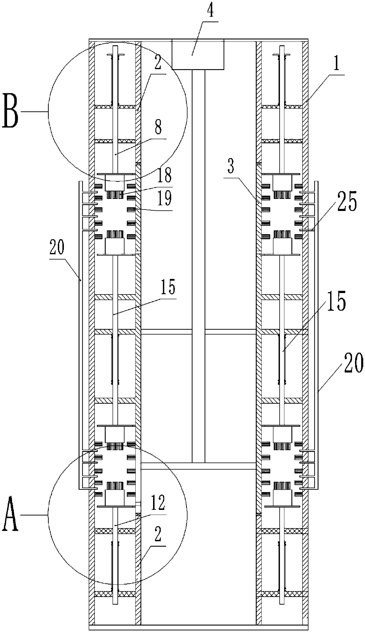
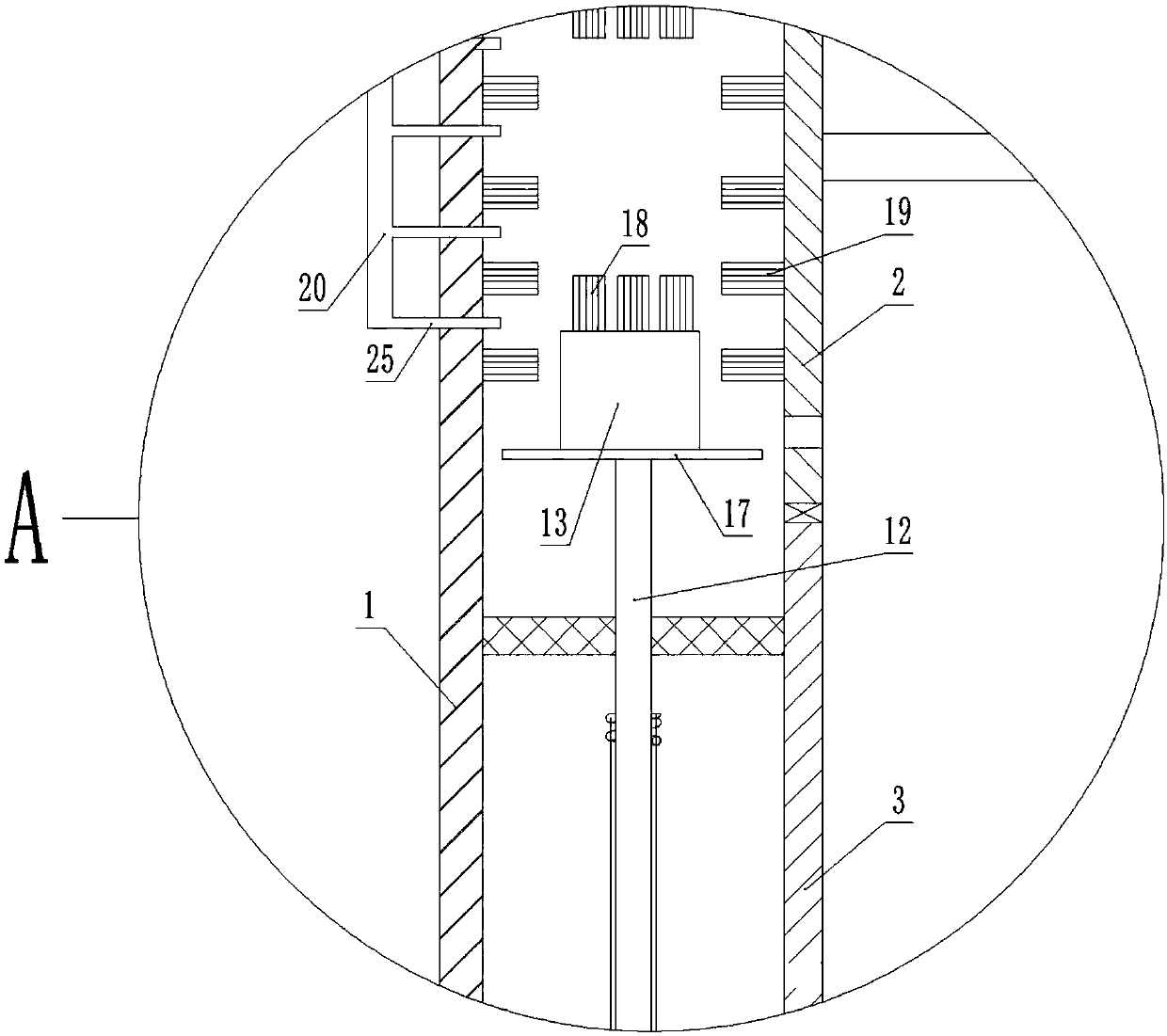
[0020] Such as Figures 1 to 5 As shown, a potato washing machine includes an outer cylinder 1, and the inner cavity of the outer cylinder 1 is provided with two fixed cylinders 2 up and down. A rotary cylinder 3 is rotatably connected between the two fixed cylinders 2 . The outer cylinder 1 is provided with a motor 4 which drives the rotating cylinder 3 to rotate. A fixing frame is arranged in the annular space between the fixing cylinder 2 and the outer cylinder 1 . The elastic suspension on the fixed frame above is provided with upper telescopic rod 8, and the elastic suspension on the fixed frame below is provided with lower telescopic rod 12. A support frame is fixedly arranged on the outer wall of the drum 3, and a middle telescopic rod 15 is elastically suspended on the support frame. The specific elastic suspension method is as follows: the upper telescopic rod 8 and the lower telescopic rod 12 are covered with springs, one end of the spring is fixed on the fixed frame


PUM


Abstract

The invention discloses a potato cleaning machine. An upper cleaning channel communicates with and a lower cleaning channel through a feeding pipe on the outer side wall of an outer cylinder; a discharge port communicating with the lower cleaning channel is arranged on the outer side wall of the outer cylinder; an upper ring and a lower ring of drainage holes are arranged on a drum; and positionsof the drainage holes correspond to the lower end positions of side brushes on the drum. According to the invention design, a water inlet pipe is opened; potatoes enter the machine from a feeding hopper; after entering the machine, the potatoes slid into a space between an upper brush and a lower brush in the upper cleaning channel; and a motor drives the drum to rotate. Therefore, the potatoes can be washed by the brushes in the lower part; under the action of friction force, the potatoes are driven to rotate; side brushes are used for cleaning the two sides of the potatoes; the upper ends ofrubber layers are wavy and grooves and bulges alternate, so that when the potatoes are clamped into the grooves on the upper side, under the buffering of springs, the potatoes can be turned over by the bulges on the lower side so as to realize all-around cleaning on the potatoes.

Description


Claims


Application Information

Patent Timeline
Owner 毕传龙
Why Eureka
Try Eureka