Power distribution cabinet

A power distribution cabinet and electric power technology, which is applied in the substation/power distribution device shell, electrical components, substation/switch layout details, etc., can solve the problems of exposed cooling fan circuit, lack of heat dissipation, danger, etc., and achieve locking and power-on safety and stability

Inactive Publication Date: 2018-04-10
王世松
View PDF0 Cites 0 Cited by
  • Summary
  • Abstract
  • Description
  • Claims
  • Application Information

AI Technical Summary

Benefits of technology

This patented technology allows for easy maintenance or replacement of electronic components such as coolers without having them be exposed during operation. It achieves this by allowing two different types of movement: one moves towards another direction while maintaining secure connection between parts; and other movements move backward along the same path again after being connected together. These actions help prevent damage caused by external factors like vibrations or impacts.

Problems solved by technology

This patented technical problem addressed in this patents relates to improving thermal performance for electricity distributing cabinets used with switching devices such as breakers that require better heat dissaporation from outside sources like wind turbines due to their large size and weight. Existing solutions have limitations including difficulty attaching them securely enough to prevent damage caused by external factors (such as rain) while also allowing easy maintenance without damaging any internal components they were designed around.

Method used


Image

  • Power distribution cabinet
  • Power distribution cabinet
  • Power distribution cabinet

Examples


Embodiment Construction

[0018] The preferred embodiments of the present invention will be described in detail below in conjunction with the accompanying drawings, so that the advantages and features of the present invention can be more easily understood by those skilled in the art, so as to define the protection scope of the present invention more clearly.

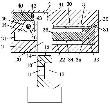
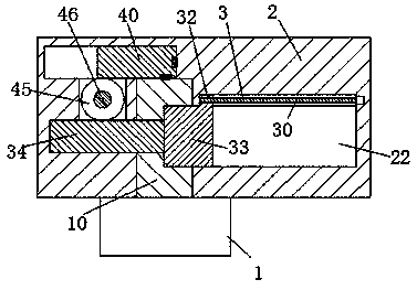
[0019] refer to Figure 1-3 As shown, a power distribution cabinet of the present invention includes a top base 2 arranged in the cabinet body 5 and a radiator 1 for mating connection with the top base 2, and the top of the radiator 1 is fixedly provided with a plug block 10, a first slot 11 is provided on the left end face of the insert block 10, a second slot 12 communicating with the first slot 11 is provided on the right end face of the insert block 10, the insert block 10 A power conduction head 13 is arranged in the middle of the top surface, and a notch 20 extending upwards and used to connect with the plug 10 is provided on the bottom surfac


PUM


Abstract

The invention discloses an electric power distribution cabinet, comprising a top seat arranged in a cabinet body and a radiator used for cooperating with the top seat, a plug block is fixedly arranged on the top of the radiator, and the left end of the plug block A first slot hole is arranged on the surface, a second slot hole communicated with the first slot hole is arranged on the right end surface of the insert block, a power conduction head is arranged in the middle of the top surface of the insert block, and the top seat bottom The end face is provided with a slot that extends upward and is used to cooperate with the insert block; in the present invention, the radiator is securely and stably fixed on the top of the cabinet, and the hot air on the top is discharged, and the heat dissipation effect is good, effectively avoiding the An electric shock accident occurs when the radiator is installed and removed, the whole device is convenient and quick to operate, and the installation and removal efficiency of the radiator is high.

Description


Claims


Application Information

Patent Timeline
Owner 王世松
Why Eureka
Try Eureka