Method and system for calculating three-dimensional depth of field based on double imaging device

An imaging device and computing method technology, applied in the field of 3D imaging, can solve problems such as video analysis that is difficult to meet fast response, heavy workload, and difficult to achieve real-time performance

Active Publication Date: 2018-04-13
VISIONERTECH CO LTD
View PDF3 Cites 0 Cited by
  • Summary
  • Abstract
  • Description
  • Claims
  • Application Information

AI Technical Summary

Problems solved by technology

However, the existing technology involves a large workload in the process of realizing binocular depth of field calculat

Method used


Image

  • Method and system for calculating three-dimensional depth of field based on double imaging device
  • Method and system for calculating three-dimensional depth of field based on double imaging device
  • Method and system for calculating three-dimensional depth of field based on double imaging device

Examples


Embodiment Construction

[0055] In order to make the purpose, technical solution and technical effect of the present invention clearer, the present invention will be further described in detail below in conjunction with the accompanying drawings and specific embodiments. It should be understood that the specific implementations described in this specification are only for explaining the present invention, not for limiting the present invention.

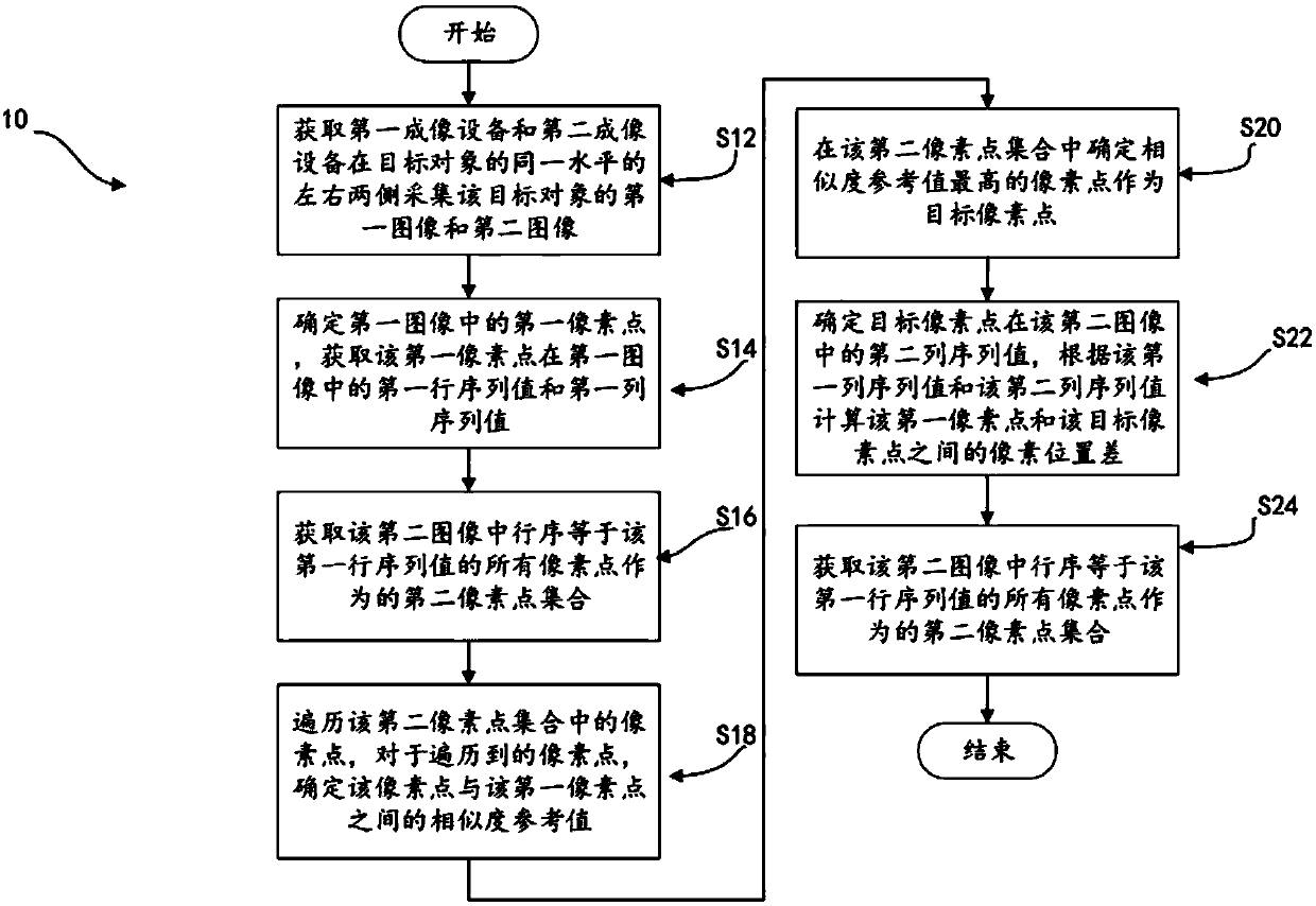
[0056] The invention discloses a calculation method 10 for three-dimensional depth of field based on dual imaging devices. Such as figure 1 As shown, the method 10 includes:

[0057]S12. Obtain a first image and a second image of the target object acquired by the first imaging device and the second imaging device on the left and right sides of the same level of the target object.

[0058] Specifically, the first imaging device and the second imaging device include but are not limited to cameras, video cameras and other devices. The first imaging device and th


PUM


Abstract

The invention relates to a method for calculating the three-dimensional depth of field based on double imaging device. The method comprises the steps of acquiring a first image and a second image, which are respectively collected by a first imaging device and a second imaging device, of a target object; determining a first pixel point in the first image, and acquiring a first row sequence value and a first column sequence value of the first pixel point; acquiring a second pixel point set in the second image; determining a pixel point with the highest similarity reference value in the second pixel point set to serve as a target pixel point; calculating the pixel position difference between the first pixel point and the target pixel point; and calculating a three-dimensional depth of field value of a point corresponding to the first pixel point and the target pixel point in the target object according to the pixel position difference. The beneficial effects lie in that the three-dimensional depth of field value of a certain point in the target object can be quickly determined according to the method for calculating the three-dimensional depth of field based on the double imaging device.

Description


Claims


Application Information

Patent Timeline
Owner VISIONERTECH CO LTD
Why Eureka
Try Eureka