Retention-free full-enclosing three-piece-type ball valve

A three-piece, ball valve technology, applied in valve details, valve device, valve shell structure, etc., can solve the problems of fluid channel corrosion, corrosion, affecting the service life of the ball valve, etc., to avoid fluid leakage and improve continuity.

Inactive Publication Date: 2018-04-17
叶良俊
View PDF0 Cites 0 Cited by
  • Summary
  • Abstract
  • Description
  • Claims
  • Application Information

AI Technical Summary

Problems solved by technology

[0003] When the existing ball valve is in use, the medium will enter the interior of the valve body along with the fluid channel, and it is difficult to ensure that the fluid will not remain inside the fluid

Method used


Image

  • Retention-free full-enclosing three-piece-type ball valve
  • Retention-free full-enclosing three-piece-type ball valve

Examples


Embodiment Construction

[0014] The following will clearly and completely describe the technical solutions in the embodiments of the present invention with reference to the accompanying drawings in the embodiments of the present invention. Obviously, the described embodiments are only some, not all, embodiments of the present invention. Based on the embodiments of the present invention, all other embodiments obtained by persons of ordinary skill in the art without making creative efforts belong to the protection scope of the present invention.

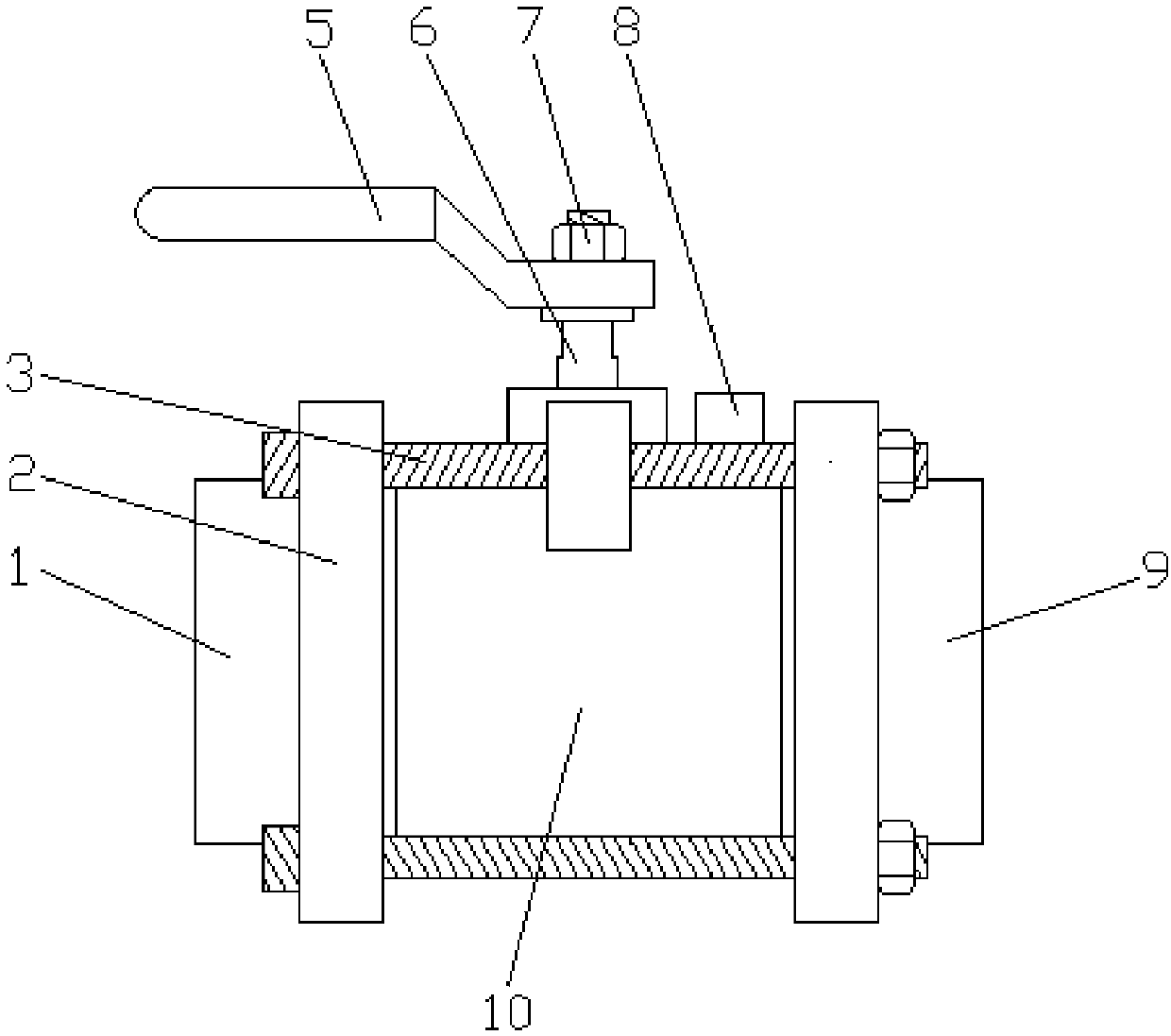
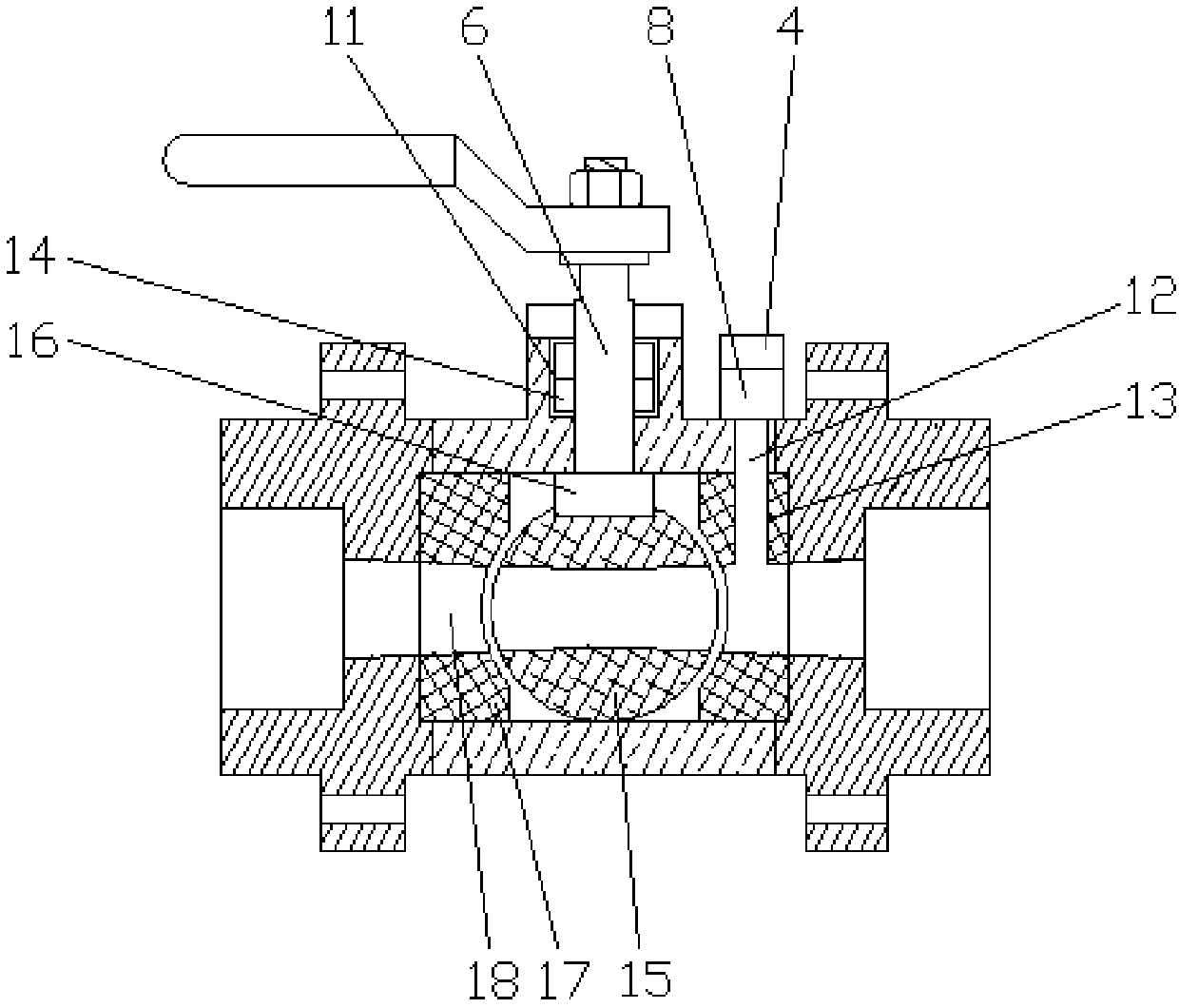
[0015] see Figure 1-2 , in an embodiment of the present invention, a non-retention all-inclusive three-piece ball valve, including a left side cover 1, a flange 2, a right side cover 9, a valve body 10, a high-pressure pipe installation groove 13, a spherical valve plate 15 and a sealing ring 17. Flanges 2 are welded on the surfaces of the left side cover 1, the right side cover 9 and the valve body 10, the valve body 10 is provided on one side of the left side


PUM


Abstract

The invention discloses a non-retention all-inclusive three-piece ball valve, which includes a left side cover, a flange, a right side cover, a valve body, a high-pressure pipe installation groove, a spherical valve plate and a sealing ring. Flanges are welded on the surface of the cover and the valve body, a valve body is provided on one side of the left side cover, a right side cover is provided on one side of the valve body, the left side cover, the right side cover and the valve body are three The other is fixedly connected by the bolts that pass through the flange, the upper part of the valve body is provided with a valve stem installation groove, the valve stem is installed inside the valve stem installation groove, and the top of the valve stem extends out of the valve stem installation groove, The bottom surface of the valve stem is welded with a valve block, and the diameter of the present invention gradually increases from the center of the spherical valve plate to both ends of the left side cover and the right side cover through the fluid channel, so that the fluid remaining in the fluid channel is under the action of gravity. The fluid gradually flows out of the valve body, and the fluid can be flushed out of the fluid channel by injecting high-pressure gas into the gas injection seat.

Description


Claims


Application Information

Patent Timeline
Owner 叶良俊
Why Eureka
Try Eureka