Current-steering digital-analog converter high-potential current source unit switch decoding circuit and method

A digital-to-analog converter and unit switch technology, applied in the direction of digital-to-analog converters, etc., can solve the problems of complicated and tedious test process, time-consuming test, increase test cost, etc., to improve dynamic performance indicators, improve SFDR, increase The effect of chip area

Inactive Publication Date: 2018-04-20
灿芯创智微电子技术(北京)有限公司
View PDF8 Cites 4 Cited by
  • Summary
  • Abstract
  • Description
  • Claims
  • Application Information

AI Technical Summary

Problems solved by technology

However, this method makes the process complicated, the test process is complica

Method used


Image

  • Current-steering digital-analog converter high-potential current source unit switch decoding circuit and method
  • Current-steering digital-analog converter high-potential current source unit switch decoding circuit and method
  • Current-steering digital-analog converter high-potential current source unit switch decoding circuit and method

Examples


Embodiment

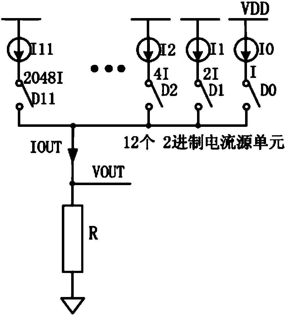
[0088] In order to make the purpose, technical solution and advantages of the present invention clearer, the specific implementation manner of the present invention will be described in detail below by taking a 12-bit DAC whose input is D11-D0 as an example.

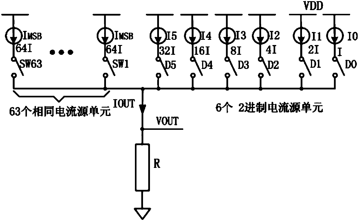
[0089] The main purpose of the present invention is to simply change the row and column decoding logic and maintain the high-speed characteristics of the current-steering digital-to-analog converter on the basis of maintaining the design of the traditional high-level current source unit using a matrix structure in the standard CMOS process. On the premise of satisfying the high-speed application, by changing the switching sequence of the current source unit, the selected current source unit has randomness. Taking the decoding of the upper 6-bit current source unit as an example, the upper 6-bit current source unit is composed of 64 identical current source units arranged in an 8X8 matrix array, which is consistent with the t


PUM


Abstract

The invention belongs to the field of current-steering digital-analog converters, and specifically relates to a current-steering digital-analog converter high-potential current source unit switch decoding circuit. The circuit is disposed on a matrix formed by high-potential current source units of a current-steering digital-analog converter, and comprises a random column decoding circuit and a random row decoding circuit. The circuit can generate a random column decoding signal and a random row decoding signal according a high-potential bit signal of an input code of the current-steering digital-analog converter DAC, and enables the high-potential current source units, corresponding to the random column decoding signal and the random row decoding signal, in the matrix to be opened. The random column decoding signal and the random row decoding signal, which are generated at each time according to the high-potential bit signals of the input code of the DAC, are different, and the openedhigh-potential current source units are different, thereby improving the performance of the SFDR (Spurious Free Dynamic Range) of the current-steering digital-analog converter, wherein the SFDR indicates the difference between input signal energy and the maximum distortion energy.

Description


Claims


Application Information

Patent Timeline
Owner 灿芯创智微电子技术(北京)有限公司
Why Eureka
Try Eureka