Automatic door opening positioning mechanism

A positioning mechanism and component technology, applied in door/window fittings, building structures, switches with braking devices, etc., can solve problems such as difficult to open the door and inconvenient use of hands

Active Publication Date: 2018-05-15
CHONGQING WEIRUI TECH CO LTD
View PDF4 Cites 0 Cited by
  • Summary
  • Abstract
  • Description
  • Claims
  • Application Information

AI Technical Summary

Benefits of technology

The technical effect described in this patented system relates to an improved method or device used inside doors without requiring manual effort from people who don't have enough strength to turn them around their armchair handle.

Problems solved by technology

This patented technical feature describes an improved design for doors used in buildings where they require automatic closing or unlatching movements between their main parts during movement within them. However, current designs have limitations due to difficulty in achieving proper alignment between the limits of motion mechanisms and the limitation imposed upon manual push actions.

Method used


Image

  • Automatic door opening positioning mechanism

Examples


Embodiment Construction

[0035] The following is a further detailed description through specific implementations:

[0036] The reference signs in the drawings of the specification include:

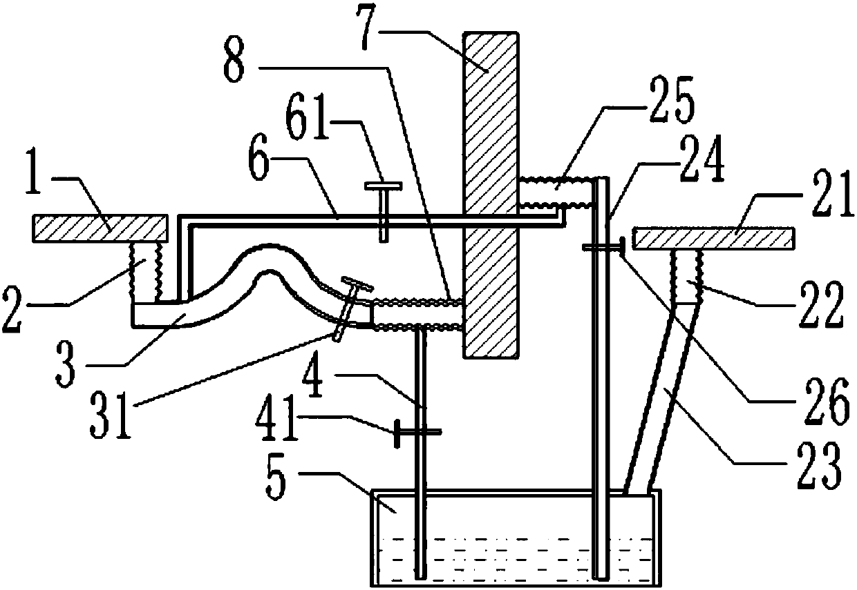
[0037] Entry sensor board 1, entry sensing bellows 2, entry S-shaped tube 3, S-shaped tube check valve 31, door opening bellows 8, inlet pipe 4, water inlet check valve 41, sealed water box 5, circulating water pipe 6, circulation One-way valve 61, door body 7, door closing sensor plate 21, door closing sensor bellows 22, air outlet pipe 23, water outlet pipe 24, door closing bellows 25, water outlet check valve 26.

[0038] The embodiment is basically like figure 1 Shown:

[0039] The self-opening door positioning mechanism of the present invention includes a door opening member, a door closing member and a circulation member;

[0040] The door opening component includes a vertical entry induction bellows 2, a horizontal entry S-shaped tube 3 and a horizontal entry opening bellows. The entry induction bellows 2 is connected


PUM


Abstract

The invention discloses an automatic door opening positioning mechanism, and belongs to the field of hinges or pivots of doors, windows or sashes. Aiming at the problems that in the prior art, doors need to be manually pushed, cover caps needs to be pressed, and the locking angle is singular, the following scheme is provided, specifically, after a door entrance induction corrugated pipe senses external pressure, water in the door entrance induction corrugated pipe is squeezed, the squeezed water gradually flows into a door opening corrugated pipe, the door opening corrugated pipe expands to push a door, and thus, the door is opened; the lower portion of the door opening corrugated pipe communicates with a water inlet pipe, and the water in the door opening corrugated pipe is slowly pouredinto a sealed water box; when a door closing induction corrugated pipe senses external pressure, air in the door closing induction corrugated pipe is compressed to enter the sealed water box, the high-pressure airflow in the sealed water box constricts waterflow to go upwards along a water outlet pipe stretching into the lower portion of the liquid level, the waterflow is injected into a door closing corrugated pipe, and accordingly, the door is pushed to be closed; and the door closing corrugated pipe internally communicates with a circulation water pipe, and the waterflow in the door closingcorrugated pipe is slowly poured into a door entrance S-shaped pipe through the circulation water pipe.

Description


Claims


Application Information

Patent Timeline
Owner CHONGQING WEIRUI TECH CO LTD
Why Eureka
Try Eureka