Lawn mower charging apparatus base plate, lawn mower charging apparatus and lawn mower system

A charging device, lawn mower technology, applied in circuit devices, battery circuit devices, current collectors, etc., can solve problems such as grass not growing smoothly, lawn damage, etc.

Inactive Publication Date: 2018-05-25
POSITEC POWER TOOLS (SUZHOU) CO LTD
View PDF5 Cites 0 Cited by
  • Summary
  • Abstract
  • Description
  • Claims
  • Application Information

AI Technical Summary

Problems solved by technology

However, due to the obstruction of the charging station, the grass under the chargi

Method used


Image

  • Lawn mower charging apparatus base plate, lawn mower charging apparatus and lawn mower system
  • Lawn mower charging apparatus base plate, lawn mower charging apparatus and lawn mower system
  • Lawn mower charging apparatus base plate, lawn mower charging apparatus and lawn mower system

Examples


Embodiment Construction

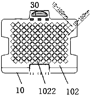
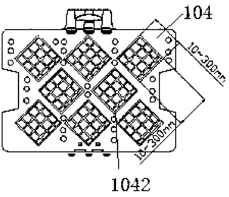
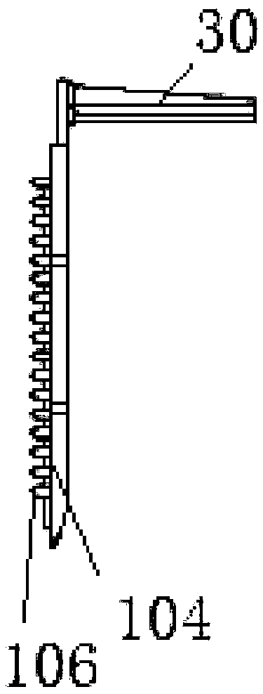
[0020] In order to facilitate the understanding of the present invention, the present invention will be described more fully below with reference to the associated drawings. Preferred embodiments of the invention are shown in the accompanying drawings. However, the present invention can be embodied in many different forms and is not limited to the embodiments described herein. On the contrary, these embodiments are provided to make the understanding of the disclosure of the present invention more thorough and comprehensive.

[0021] It should be noted that when an element is said to be "fixed" to another element, it may be directly on the other element or there may be an element in between. When an element is referred to as being "connected to" another element, it can be directly connected to the other element or there may be both elements in between.

[0022] Unless otherwise defined, all technical and scientific terms used herein have the same meaning as commonly understood b


PUM


Abstract

The invention discloses a lawn mower charging apparatus base plate which includes a first surface and a second surface which are opposite to each other. The first surface is perforated with a first aperture. The second surface is perforated with a second aperture that is in communication with the first aperture. The lawn mower charging apparatus base plate is provided with the first aperture and the second aperture thereon, so that the grass below the lawn mower charging apparatus base plate can extend above the lawn mower charging apparatus base plate through the first aperture and the secondaperture. Therefore, the setting of the lawn mower charging apparatus base plate does not affect the growth of grass and does not damage the lawn. The invention also discloses a lawn mower charging apparatus and a lawn mower system. The lawn mower charging apparatus also includes a lawn mower charging apparatus base plate and a charging part. The charging part is disposed on the lawn mower charging apparatus base plate. The lawn mower system includes a lawn mower body and the aforementioned lawn mower charging apparatus.

Description


Claims


Application Information

Patent Timeline
Owner POSITEC POWER TOOLS (SUZHOU) CO LTD
Why Eureka
Try Eureka