Ocean atmospheric optical parameter measurement method and equipment
A technology of optical parameters and measurement methods, applied in the field of optical detection, can solve the problems of reducing measurement accuracy, limitation of aerosol measurement, affecting water color remote sensing data measurement, etc., to achieve the effect of improving accuracy and monitoring effect
- Summary
- Abstract
- Description
- Claims
- Application Information
AI Technical Summary
Problems solved by technology
Method used
Image

Examples
Embodiment 1
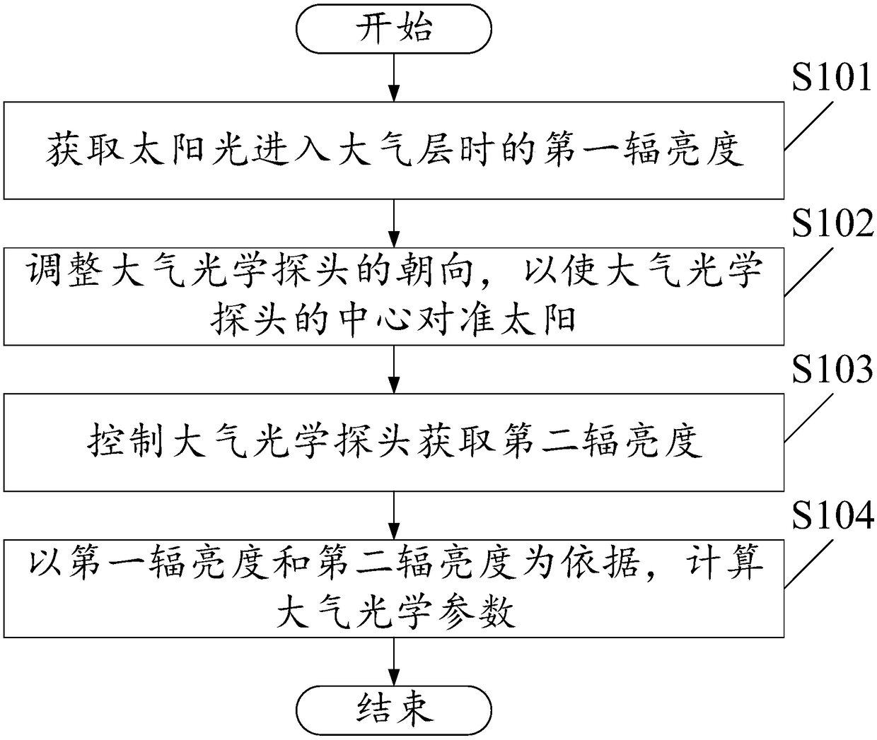
[0055] see figure 1 , figure 1 It is a schematic flowchart of a method for measuring ocean-atmosphere optical parameters provided in this embodiment. Such as figure 1 As shown, the measurement method includes the following steps:
[0056] S101. Obtain the first radiance of sunlight when it enters the atmosphere.
[0057] In this embodiment, the first radiance is a known radiance parameter, so it can be obtained directly, and no further details are given in this embodiment.
[0058] In this embodiment, the execution device may be an atmospheric optical probe, a control terminal (such as a mobile phone, a computer), or a central control platform, which is not limited in this embodiment.
[0059] In this embodiment, the method for obtaining the first radiance may include downloading from the network, may also include extracting from data, and may also include calculating based on physical quantities, which is not limited in this embodiment.
[0060] In this embodiment, the firs
Embodiment 2
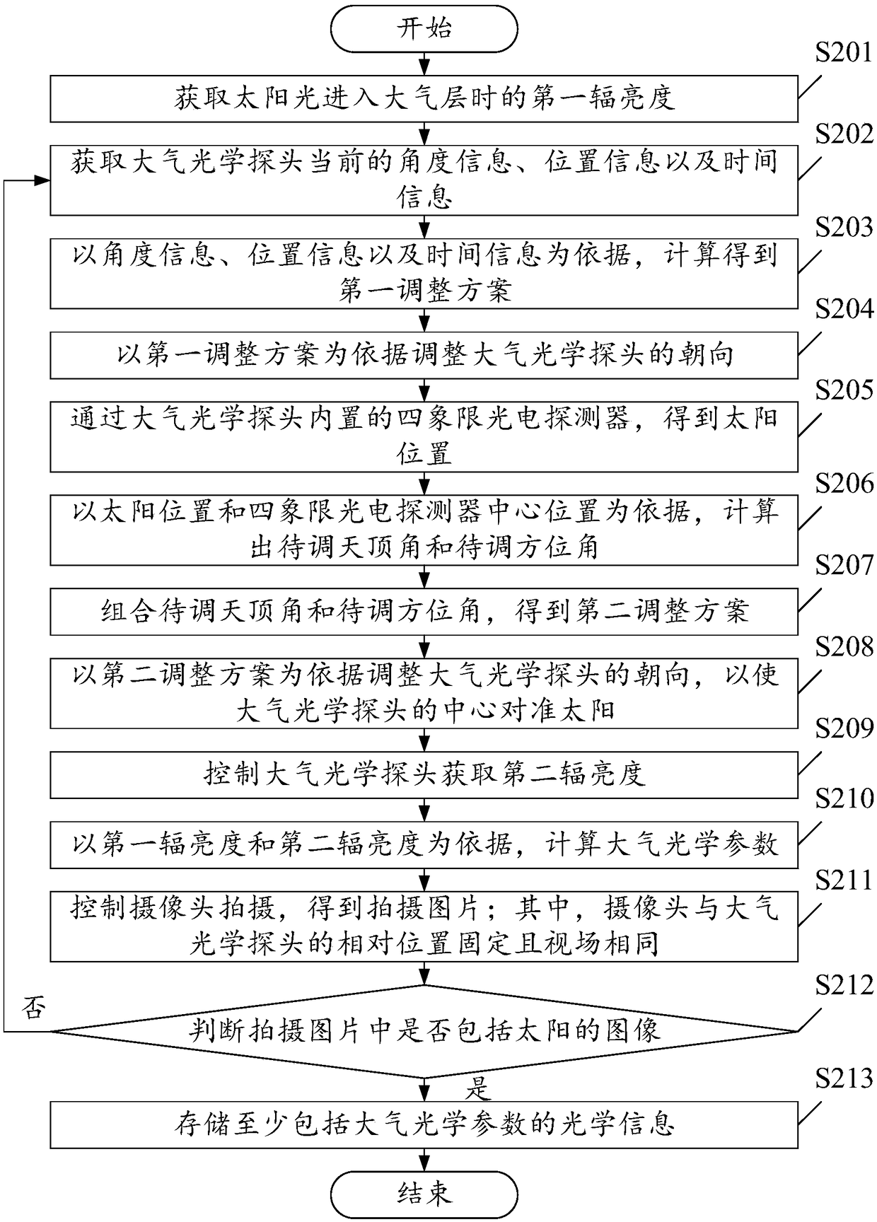
[0086] see figure 2 , figure 2 is a schematic flow chart of the measurement method provided in this embodiment. Such as figure 2 As shown, the measurement method includes the following steps:
[0087] S201. Obtain the first radiance of sunlight when it enters the atmosphere.
[0088] As an optional implementation, after obtaining the first radiance of sunlight entering the atmosphere, the measurement method may also include:
[0089] Measure the balance parameters of the measuring equipment through the built-in electronic balancer, judge whether the measuring equipment is in a balanced state according to the balanced parameters, and if it is in a balanced state, perform the next steps.
[0090] By implementing this embodiment, the balance state of the measuring device can be detected, so as to determine whether the measuring device is in a shaken state, and the subsequent step of acquiring optical data is performed when the measuring device is not in a shaken state. In th
Embodiment 3
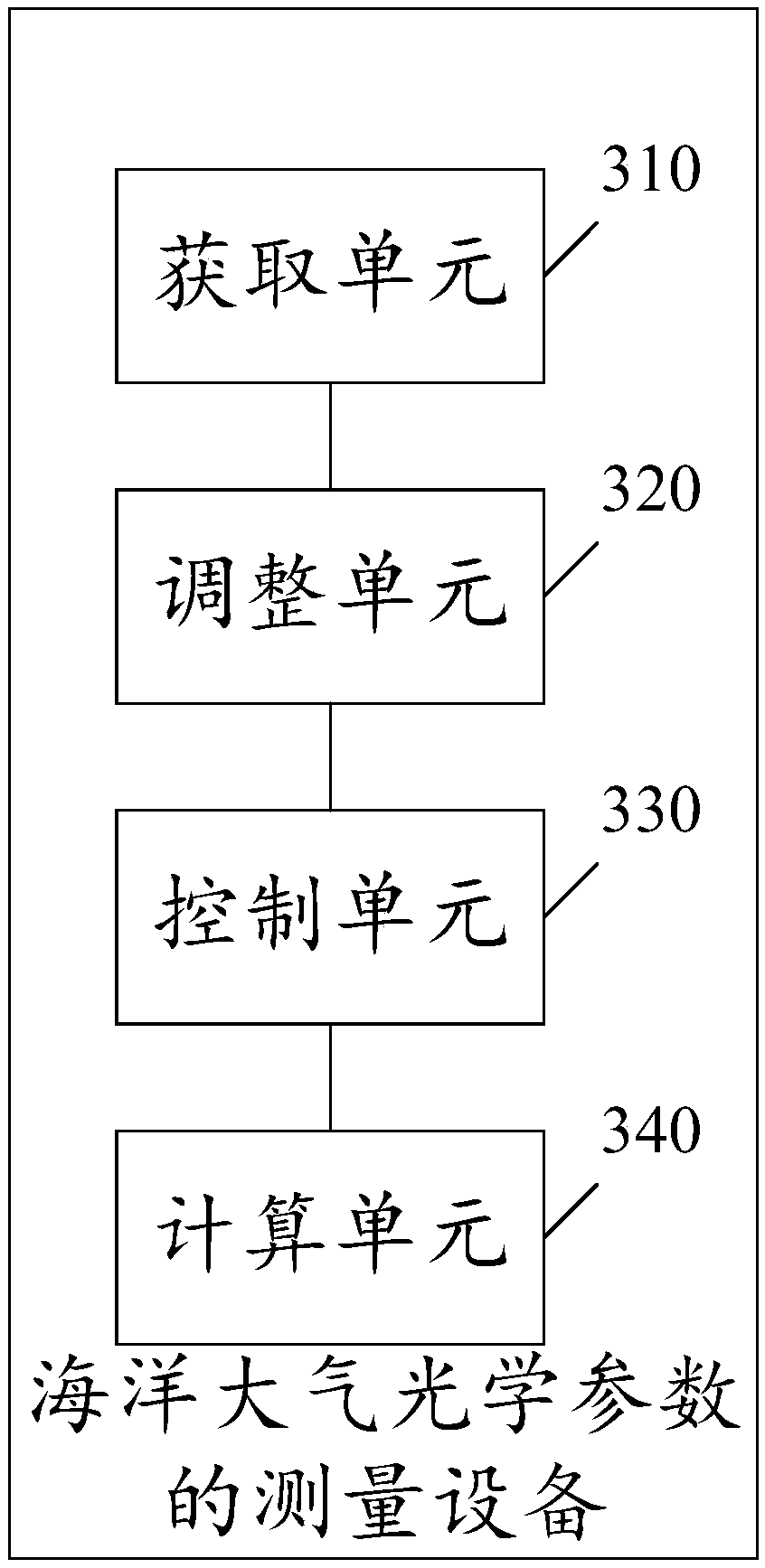
[0121] see image 3 , image 3 It is a structural schematic diagram of the measurement equipment for the ocean-atmosphere optical parameters provided in this embodiment. Such as image 3 As shown, the measuring equipment includes:
[0122] The acquisition unit 310 is configured to acquire the first radiance of sunlight when it enters the atmosphere.
[0123] The adjustment unit 320 is configured to adjust the orientation of the atmospheric optical probe so that the center of the atmospheric optical probe is aligned with the sun.
[0124] The control unit 330 is configured to control the atmospheric optical probe to acquire the second radiance.
[0125] The calculation unit 340 is configured to calculate atmospheric optical parameters based on the first radiance and the second radiance.
[0126] see Figure 4 , Figure 4 It is another structural schematic diagram of the measurement equipment for the ocean-atmosphere optical parameters provided in this embodiment. Such as
PUM
 Abstract
Description
Claims
Application Information
 - R&D Engineer
- R&D Manager
- IP Professional
- Industry Leading Data Capabilities
- Powerful AI technology
- Patent DNA Extraction
Browse by: Latest US Patents, China's latest patents, Technical Efficacy Thesaurus, Application Domain, Technology Topic.
© 2024 PatSnap. All rights reserved.Legal|Privacy policy|Modern Slavery Act Transparency Statement|Sitemap