Portable gasoline filling device
A kind of filling equipment and convenient technology, applied in the direction of rigid container, special dispensing device, bottle/can parts, etc., can solve the problems of not being able to observe the remaining oil amount, not being able to recycle the remaining gasoline, etc.
- Summary
- Abstract
- Description
- Claims
- Application Information
AI Technical Summary
Problems solved by technology
Method used
Image

Examples
Embodiment 1
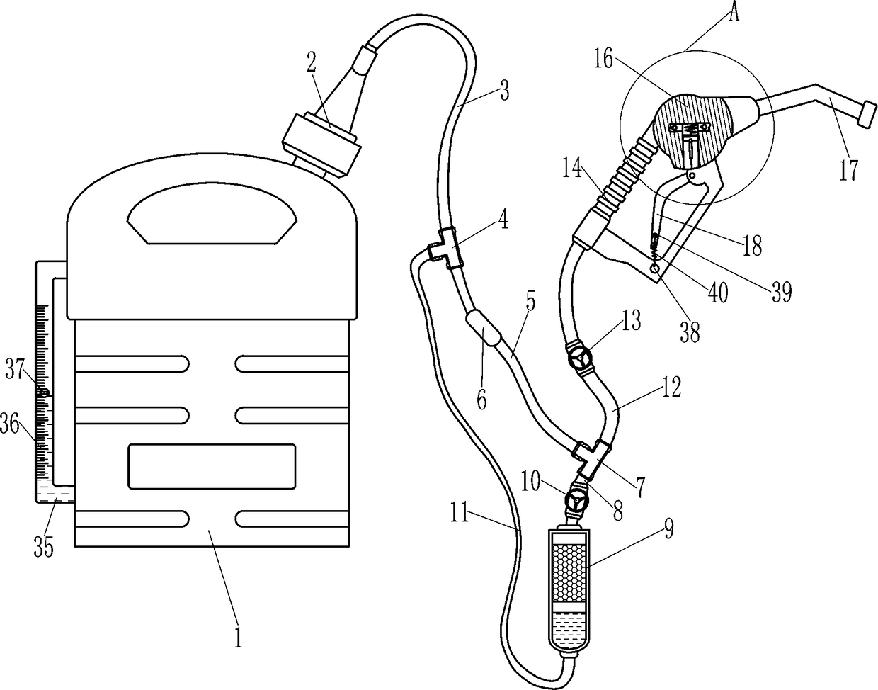
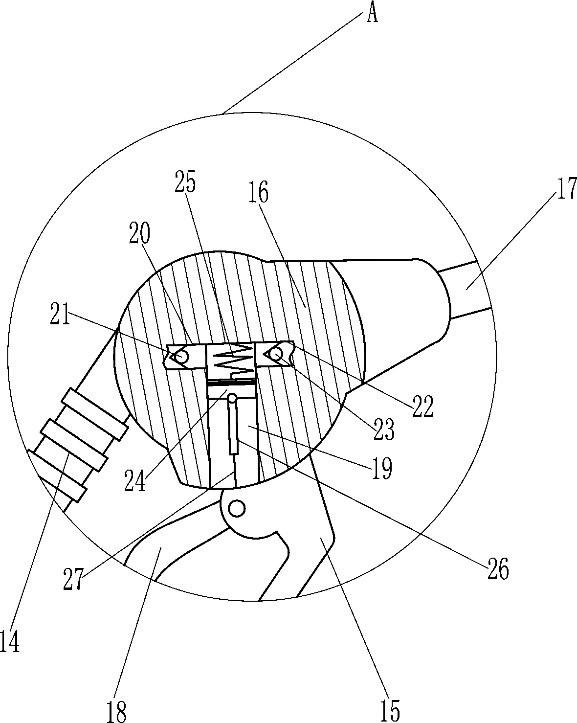
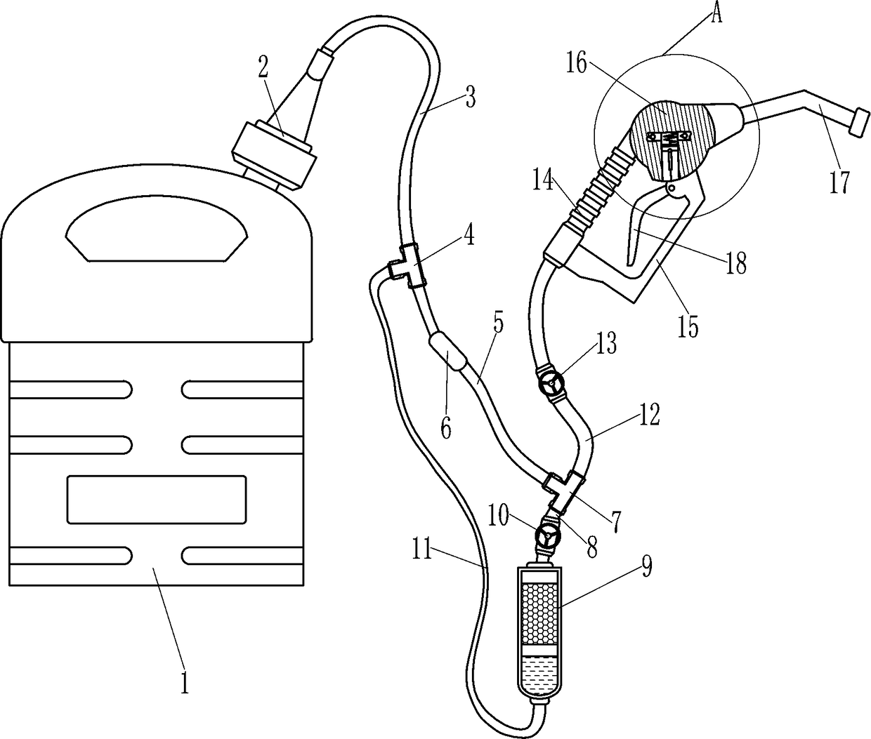
[0020] A portable gasoline filling equipment, such as Figure 1-4As shown, it includes an oil barrel 1, a connecting sleeve 2, a first hose 3, a first three-point adapter 4, a second hose 5, a check valve 6, a second three-point adapter 7, and a third hose 8. Carbon canister 9, first valve 10, fourth hose 11, fifth hose 12, second valve 13, hollow handle 14, mounting seat 15, mounting body 16, fuel injection pipe 17, handle 18, the first A one-way valve 21, a second one-way valve 23, a first piston 24, a first return spring 25, a first pull rod 26 and a pull wire 27, the upper right part of the oil barrel 1 is connected with a connecting sleeve 2, and the upper end of the connecting sleeve 2 is connected to There is a first hose 3, the first hose 3 communicates with the oil barrel 1 through the connecting sleeve 2, the lower part of the first hose 3 is connected with the first three-point adapter 4, and the lower end of the first three-point adapter 4 is connected with the second
Embodiment 2
[0022] A portable gasoline filling equipment, such as Figure 1-4 As shown, it includes an oil barrel 1, a connecting sleeve 2, a first hose 3, a first three-point adapter 4, a second hose 5, a check valve 6, a second three-point adapter 7, and a third hose 8. Carbon canister 9, first valve 10, fourth hose 11, fifth hose 12, second valve 13, hollow handle 14, mounting seat 15, mounting body 16, fuel injection pipe 17, handle 18, the first A one-way valve 21, a second one-way valve 23, a first piston 24, a first return spring 25, a first pull rod 26 and a pull wire 27, the upper right part of the oil barrel 1 is connected with a connecting sleeve 2, and the upper end of the connecting sleeve 2 is connected to There is a first hose 3, the first hose 3 communicates with the oil barrel 1 through the connecting sleeve 2, the lower part of the first hose 3 is connected with the first three-point adapter 4, and the lower end of the first three-point adapter 4 is connected with the secon
Embodiment 3
[0025] A portable gasoline filling equipment, such as Figure 1-4 As shown, it includes an oil barrel 1, a connecting sleeve 2, a first hose 3, a first three-point adapter 4, a second hose 5, a check valve 6, a second three-point adapter 7, and a third hose 8. Carbon canister 9, first valve 10, fourth hose 11, fifth hose 12, second valve 13, hollow handle 14, mounting seat 15, mounting body 16, fuel injection pipe 17, handle 18, the first A one-way valve 21, a second one-way valve 23, a first piston 24, a first return spring 25, a first pull rod 26 and a pull wire 27, the upper right part of the oil barrel 1 is connected with a connecting sleeve 2, and the upper end of the connecting sleeve 2 is connected to There is a first hose 3, the first hose 3 communicates with the oil barrel 1 through the connecting sleeve 2, the lower part of the first hose 3 is connected with the first three-point adapter 4, and the lower end of the first three-point adapter 4 is connected with the secon
PUM
 Abstract
Description
Claims
Application Information
 - R&D Engineer
- R&D Manager
- IP Professional
- Industry Leading Data Capabilities
- Powerful AI technology
- Patent DNA Extraction
Browse by: Latest US Patents, China's latest patents, Technical Efficacy Thesaurus, Application Domain, Technology Topic.
© 2024 PatSnap. All rights reserved.Legal|Privacy policy|Modern Slavery Act Transparency Statement|Sitemap