Auxiliary frame vehicle body mounting bracket
A technology for installing brackets and sub-frames, which is applied to vehicle components, transportation and packaging, and substructures. It can solve the problems of inability to adjust the height direction, large assembly size deviation, and poor stability, and achieve labor and kinetic energy savings. Effects of cost, strength improvement, and stability improvement
- Summary
- Abstract
- Description
- Claims
- Application Information
AI Technical Summary
Problems solved by technology
Method used
Image

Examples
Embodiment 1
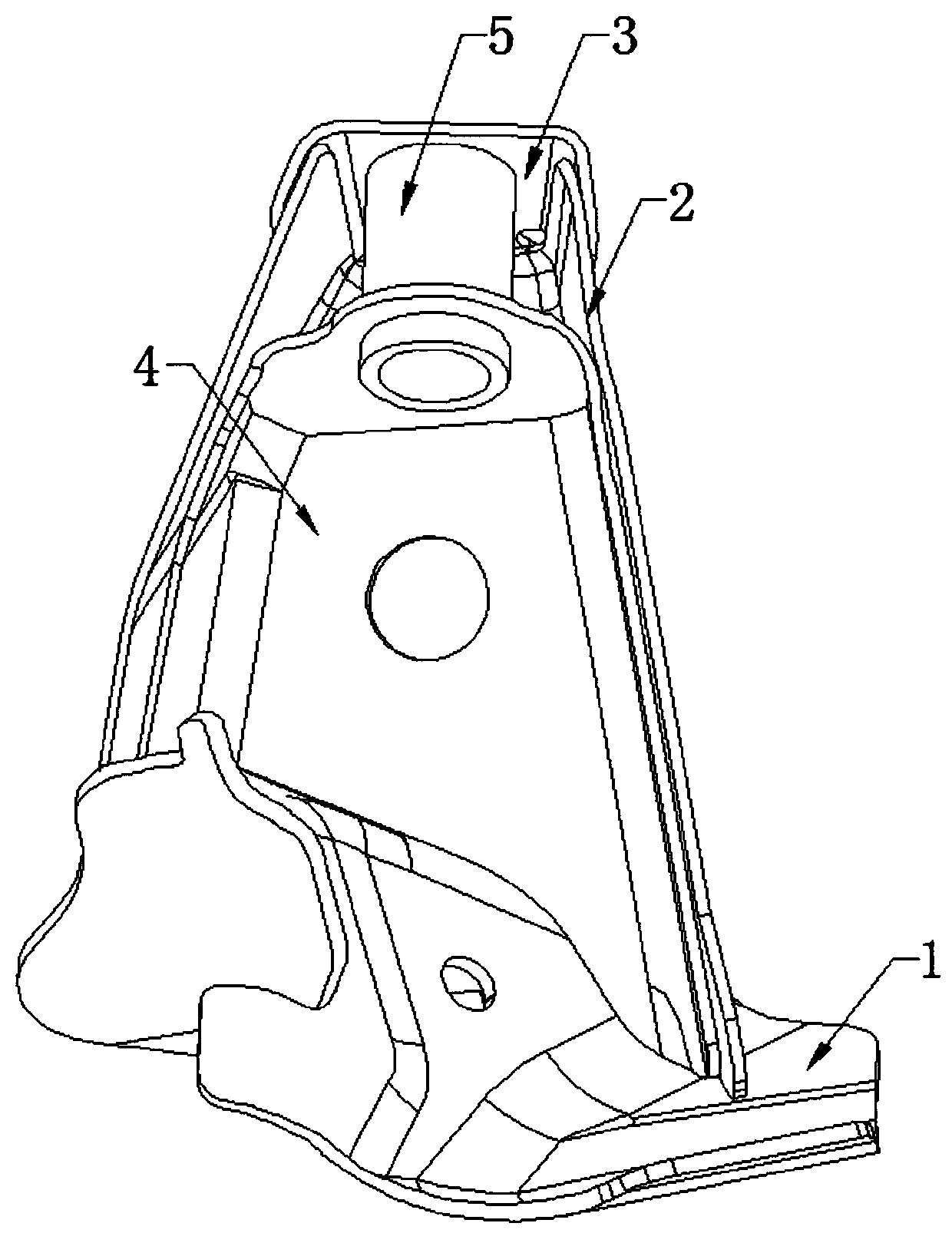
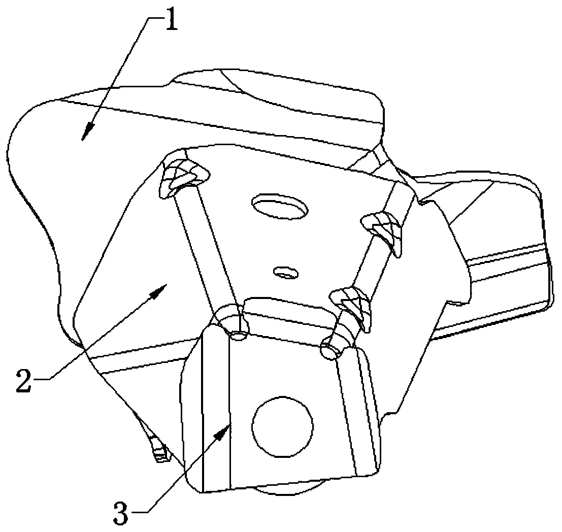
[0033] Such as Figure 1 to Figure 12 As shown, a sub-frame body mounting bracket includes a sheet metal part 1, a sheet metal part 2, a sheet metal part 3, and a sheet metal part 4,
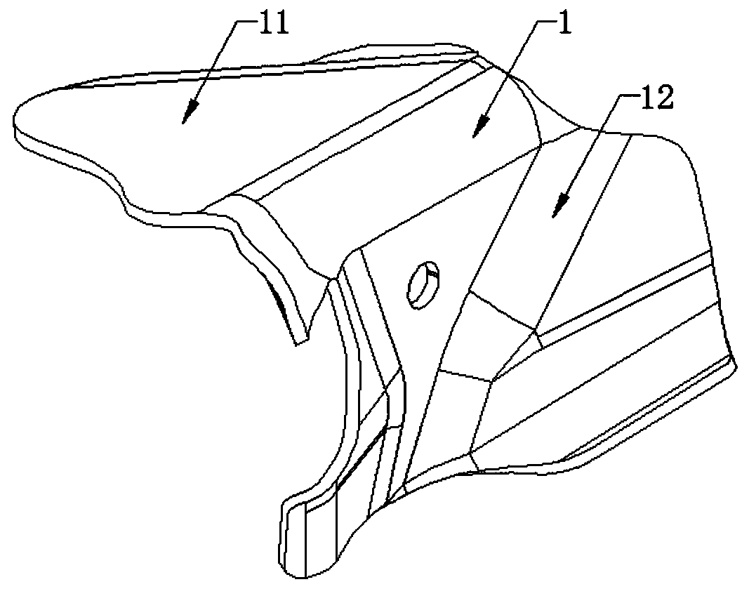
[0034] The sheet metal part 1 is provided with a left bending surface 11 and a right bending surface 12 on its left and right sides after being bent downwards. The left and right sides are respectively provided with the second left bending surface 21 and the second right bending surface 22, the sheet metal member 33 is bent downwards and the rear side and the left and right sides are respectively provided with a third rear bending surface 31. The third left bending surface 32 and the third right bending surface 33, the sheet metal part 440 is bent forward and is provided with a fourth upper bending surface 41 and a fourth left bending surface on the top and left and right sides respectively. Curved surface 42 and the fourth right bending surface 43;
[0035] The sheet metal part 3 3 is arranged above
Embodiment 2
[0041] Such as Figure 1 to Figure 12 As shown, a sub-frame body mounting bracket includes a sheet metal part 1, a sheet metal part 2, a sheet metal part 3, and a sheet metal part 4,
[0042] The sheet metal part 1 is provided with a left bending surface 11 and a right bending surface 12 on its left and right sides after being bent downwards. The left and right sides are respectively provided with the second left bending surface 21 and the second right bending surface 22, the sheet metal member 33 is bent downwards and the rear side and the left and right sides are respectively provided with a third rear bending surface 31. The third left bending surface 32 and the third right bending surface 33, the sheet metal part 440 is bent forward and is provided with a fourth upper bending surface 41 and a fourth left bending surface on the top and left and right sides respectively. Curved surface 42 and the fourth right bending surface 43;
[0043] The sheet metal part 3 3 is arranged above
PUM
 Abstract
Description
Claims
Application Information
 - R&D Engineer
- R&D Manager
- IP Professional
- Industry Leading Data Capabilities
- Powerful AI technology
- Patent DNA Extraction
Browse by: Latest US Patents, China's latest patents, Technical Efficacy Thesaurus, Application Domain, Technology Topic.
© 2024 PatSnap. All rights reserved.Legal|Privacy policy|Modern Slavery Act Transparency Statement|Sitemap