Test device

A technology of testing equipment and electronic equipment, applied in the direction of circuit breaker testing, etc., can solve the problems of manpower and time consumption, low accuracy, etc., and achieve the effect of high accuracy, fast implementation, and improved test efficiency

Active Publication Date: 2019-08-06
OPPO CHONGQING INTELLIGENT TECH CO LTD
View PDF14 Cites 0 Cited by
  • Summary
  • Abstract
  • Description
  • Claims
  • Application Information

AI Technical Summary

Benefits of technology

This technology allows for automatic movement or pressure-based tests by driving an electronics device onto another object without requiring human input during each step. It also includes features like buttons that help make it easier to perform these functions accurately through mechanical means alone.

Problems solved by technology

The technical problem addressed by this patented technology relates to improving the speed at which tests can be performed manually on electronics devices without being affected negatively or causing any issues with them over time due to lacking or incorrect data during these procedures.

Method used


Image

  • Test device
  • Test device
  • Test device

Examples


Embodiment Construction

[0016] The following will clearly and completely describe the technical solutions in the embodiments of the application with reference to the drawings in the embodiments of the application. Apparently, the described embodiments are only part of the embodiments of the application, not all of them. Based on the implementation manners in this application, all other implementation manners obtained by persons of ordinary skill in the art without making creative efforts belong to the scope of protection of this application.

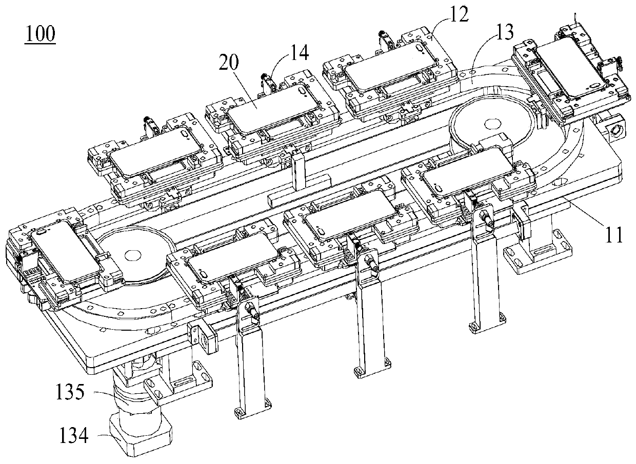
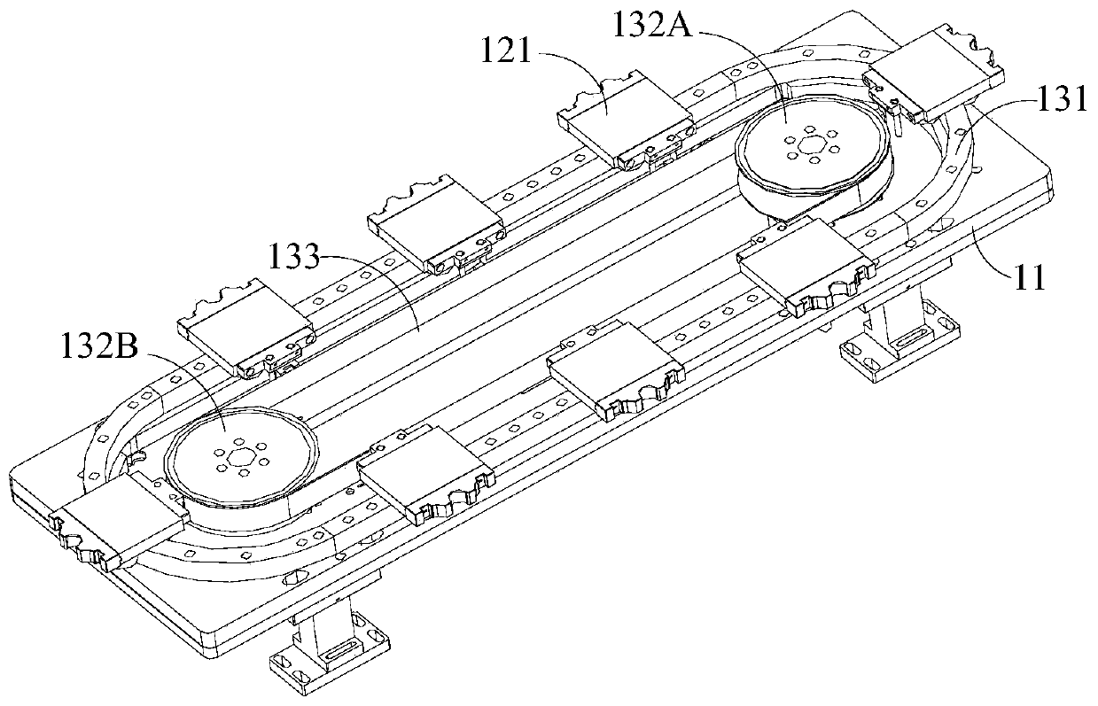
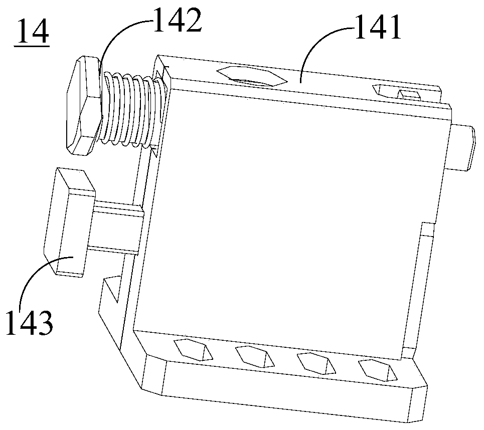
[0017] refer to figure 1 and Figure 7 , the present application provides a test device 100 for testing the working state of the electronic device 20 , the test device 100 includes: a base 11 , a carrying mechanism 12 , a transmission mechanism 13 and a pressing mechanism 14 . The transmission mechanism 13 is arranged on the base 11 . At least one carrying mechanism 12 is connected to the transmission mechanism 13 , the carrying mechanism 12 is used to carry the


PUM


Abstract

The application discloses a test device for testing the operating state of an electronic device. The test device comprises a base, a transmission mechanism disposed on the base, at least one carryingmechanism connected to the transmission mechanism, and a pressing mechanism arranged on the carrying mechanism. The carrying mechanism is used for carrying an electronic device; and the transmission mechanism is used for driving the carrying mechanism to move relative to the base. The pressing mechanism is used for pressing keys on the electronic device to control the operating state of the electronic device. Therefore, the e test efficiency can be greatly improved; automation of the key function test is realized; the key function testing can be quickly realized; and the accuracy is higher.

Description


Claims


Application Information

Patent Timeline
Owner OPPO CHONGQING INTELLIGENT TECH CO LTD
Why Eureka
Try Eureka